Permanent-magnetism synchronous motor permanent magnetic field aberration real-time detection and analysis method and device

A technology of permanent magnet synchronous motor and permanent magnet magnetic field, which is applied in the field of motion servo, and can solve problems such as loss of magnetization, reduction of sinusoidal waveform amplitude, ignoring magnetic field fluctuation and non-sinusoidal distortion of waveform

Inactive Publication Date: 2008-03-26
TSINGHUA UNIV
View PDF1 Cites 68 Cited by
  • Summary
  • Abstract
  • Description
  • Claims
  • Application Information

AI Technical Summary

Problems solved by technology

[0003] Compared with the electric excitation motor, the biggest disadvantage of the current permanent magnet motor is the permanent magnet magnetic field fluctuation and loss of magnetization: due to the low Curie temperature of the NdFeB permanent magnet material, the temperature stability is poor, and its irreversible loss and temperature coefficient are both low. Higher, resulting in serious magnetic loss at high temperature, and cannot guarantee that the demagnetization curve is a straight line, when the motor starts, brakes or fails, the current surges, and the working point will move to the knee point of the demagnetization curve, resulting in irreversible demagnetization
[0006] The existing Chinese invention patent (CN 1830135A) uses the q-axis voltage control amount used in the permanent magnet synchronous motor control to roughly estimate the demagnetization amount of the permanent magnet synchronous motor. The estimation accuracy is limited, and only the sinusoidal The amplitude of the waveform is reduced, without considering the fluctuation of the magnetic field and the non-sinusoidal distortion of the waveform

Method used


Image

  • Permanent-magnetism synchronous motor permanent magnetic field aberration real-time detection and analysis method and device
  • Permanent-magnetism synchronous motor permanent magnetic field aberration real-time detection and analysis method and device
  • Permanent-magnetism synchronous motor permanent magnetic field aberration real-time detection and analysis method and device

Examples


Embodiment Construction

[0046] Specific embodiments of the present invention will be further described below.

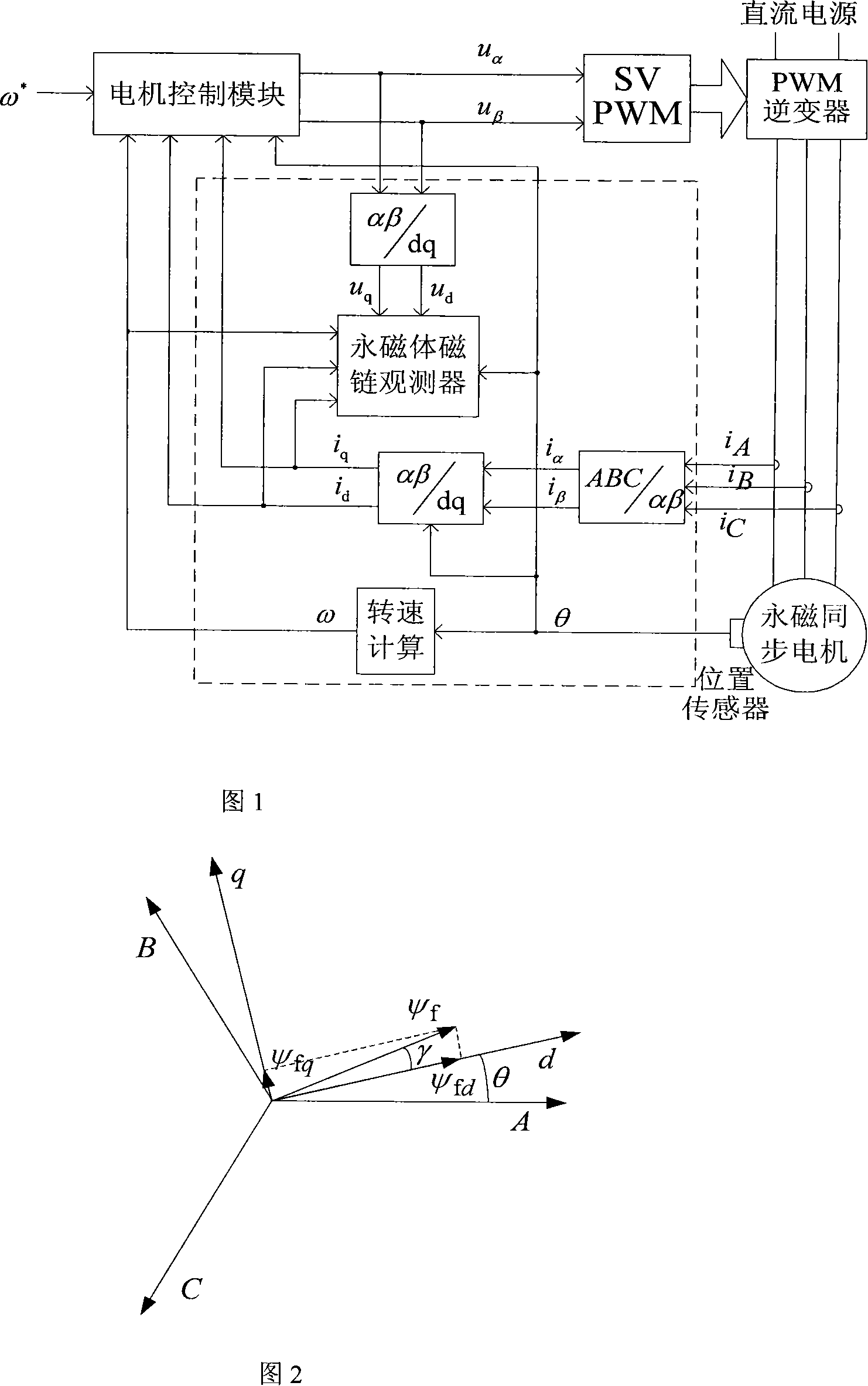
[0047] Figure 1 is a block diagram of a permanent magnet synchronous motor control system including a real-time detection method for permanent magnet flux linkage. Taking the commonly used three-phase motor as an example, it consists of a motor control module, a SVPWM module, a PWM inverter, a permanent magnet flux observer with a software program for real-time detection of permanent magnetic field distortion and distortion analysis, a position sensor, and a permanent magnet motor. ; Among them, the output of the motor control module is respectively connected to the permanent magnet flux observer and the SVPWM module, and the output of the SVPWM module is connected to the PWM inverter to control the permanent magnet motor; the position sensor is installed on the permanent magnet motor to output the position feedback signal To the motor control module; the stator current i of the permanent m...


PUM


Abstract

This invention relates to detecting, analyzing method and devices of permanent magnetic field deformation in permasyn motor. It is in the electric machine control technique field. This method is based on signals which are easy to detect such as voltage, current, electric engine rotate speed, location of the rotor, and so on. To get a real-time observation to the changing state of permasyn motor permanent magnetic field and calculate the back electromotive force coefficient, the permanent magnetic flux linkage on magnetic field synchronous revolution dq coordinate system of permasyn motor. Then the harmonic component in permanent magnetic waveform reflected motor phase winding back electromotive force coefficient by analyzing the back electromotive force. According as those methods, the optimizing control can be applied to forecast and prevent status of excitation losing in permasyn motor. The outcome has already reached can apply to excitation losing online detecting and high performance control of electric engines.

Description

technical field [0001] The invention relates to a magnetic field detection and analysis method of a motor, which belongs to the technical field of motion servo. Background technique [0002] With the continuous improvement and improvement of the performance of permanent magnet materials and the gradual maturity of the research and development experience of permanent magnet motors, permanent magnet synchronous motors are developing towards high power, high performance and miniaturization. Due to the use of permanent magnets to provide air gap flux, permanent magnet synchronous motors have the advantages of simple structure, small size, light weight, small loss, and high efficiency. It has been widely used in hybrid electric vehicles, ship propulsion, high-performance servo control and other fields. [0003] Compared with the electric excitation motor, the biggest disadvantage of the current permanent magnet motor is the permanent magnet magnetic field fluctuation and loss of...

Claims


Application Information

Patent Timeline
Patent Type & Authority Applications(China)
IPC IPC(8): G01R33/02G01R33/12G01R31/34G01R23/16H02P6/00H02P6/10
Inventor 肖曦张猛
Owner TSINGHUA UNIV
Why Eureka
Try Eureka