Electric energy-stored transmission and function implementing method thereof

A realization method and transmission technology, applied in electric brakes/clutches, collectors, electric vehicles, etc., can solve problems such as increased control complexity, increased system mechanisms, and unfavorable fuel efficiency, and achieve reduction of mechanical transmission components and simple control , The effect of good output torque characteristics

Inactive Publication Date: 2008-04-09
黄建民
View PDF5 Cites 6 Cited by
  • Summary
  • Abstract
  • Description
  • Claims
  • Application Information

AI Technical Summary

Problems solved by technology

However, the hybrid drive system of this power distribution mechanism can only charge the power storage system through the first motor / generator, and the second motor / generator can drive the wheels electrically. The second motor / generator needs to be Large motors are required to ensure adequate drive performance
In order to overcome this shortcoming, it is necessary to add a transmission mechanism to the system, and a transmission with a step difference cannot achieve the best torque matching in real time in the entire driving range of the vehicle speed
The hydraulically driven continuously variable transmission mechanism with an electric hydraulic pump requires additional energy consumption, which is not conducive to improving fuel efficiency
The hybrid drive system with the addition of multiple functional units not only increases the structure of the entire system, but also increases the complexity of control, and also increases the manufacturing cost.

Method used


Image

  • Electric energy-stored transmission and function implementing method thereof
  • Electric energy-stored transmission and function implementing method thereof
  • Electric energy-stored transmission and function implementing method thereof

Examples


Embodiment Construction

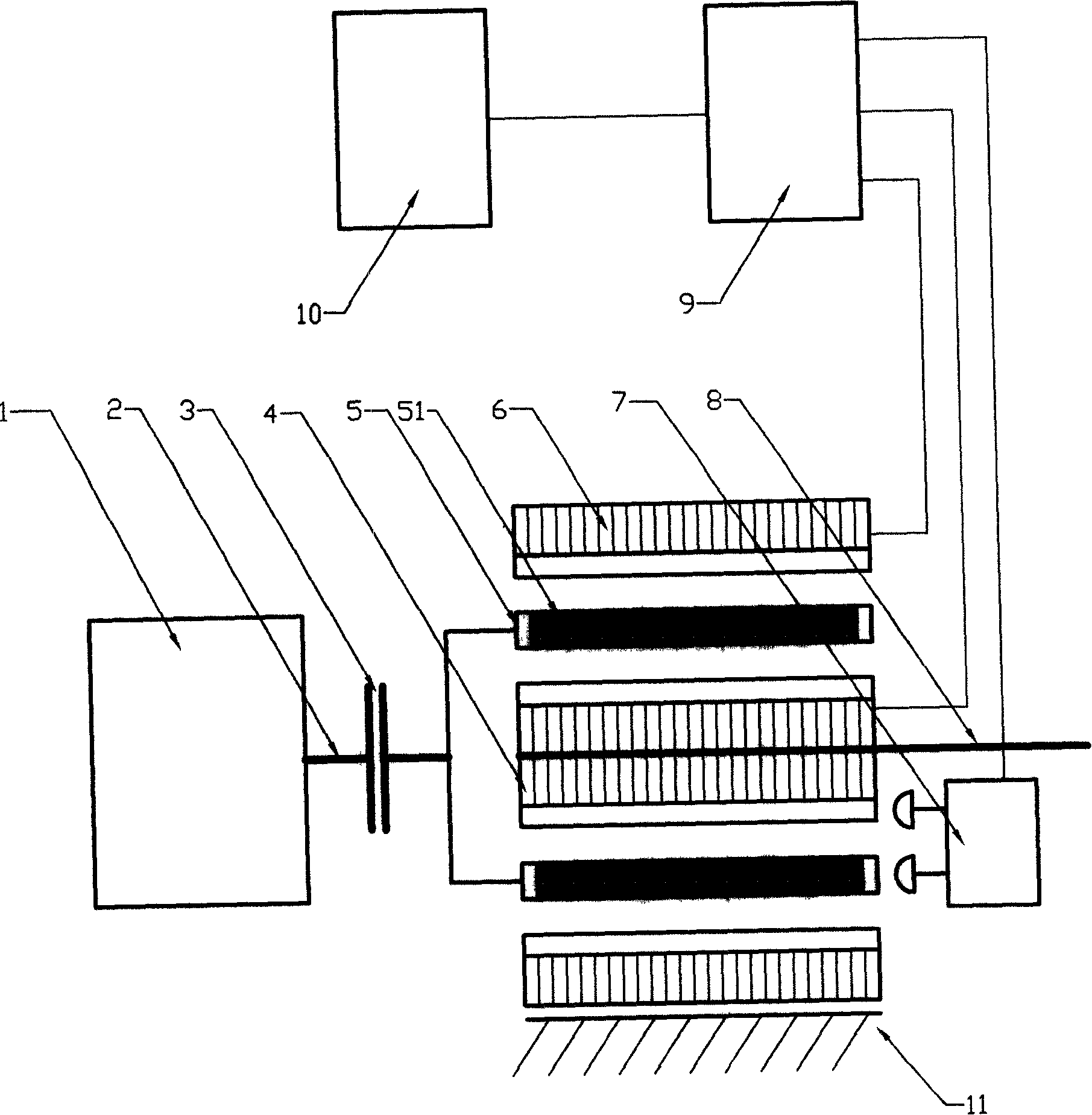
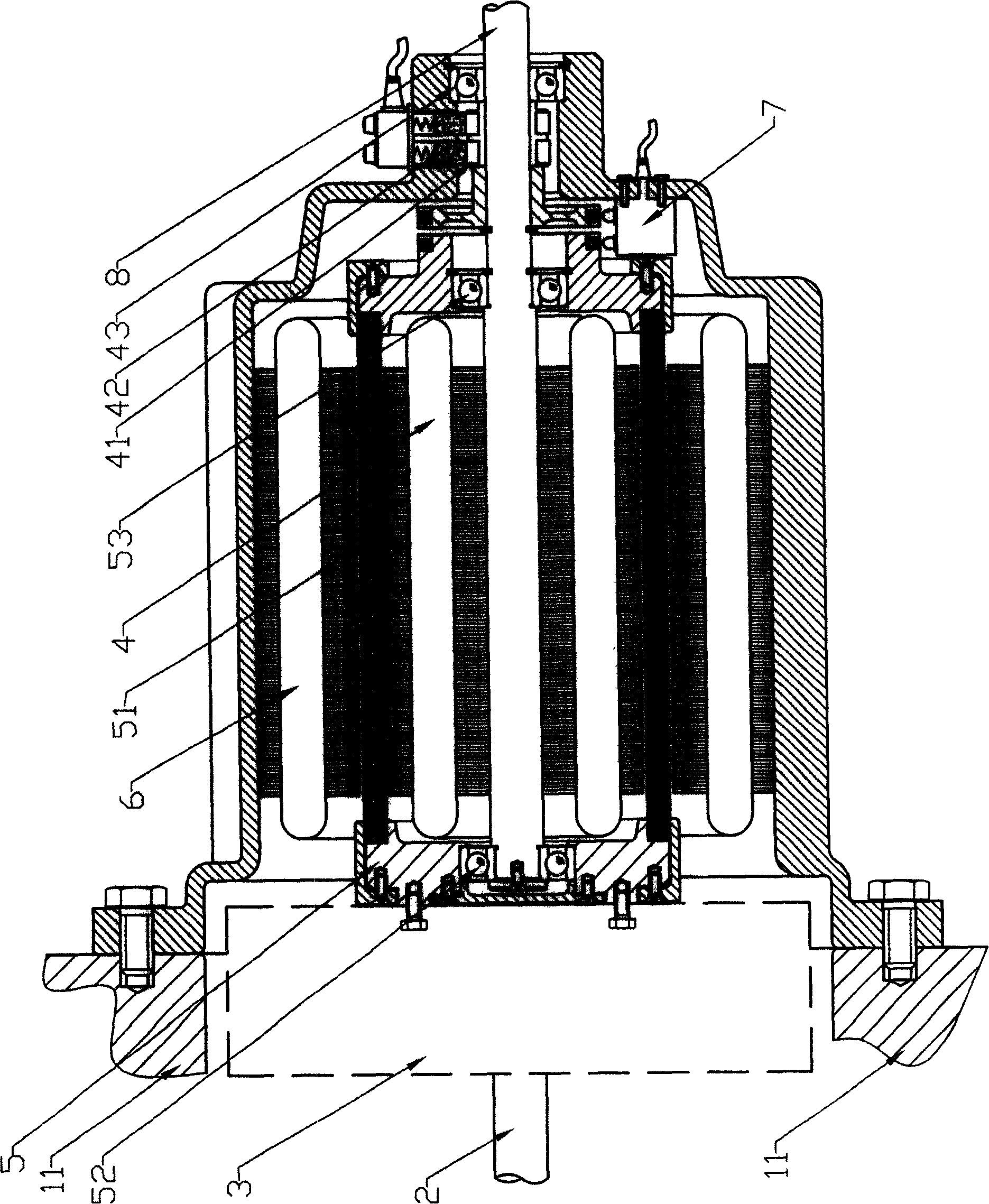
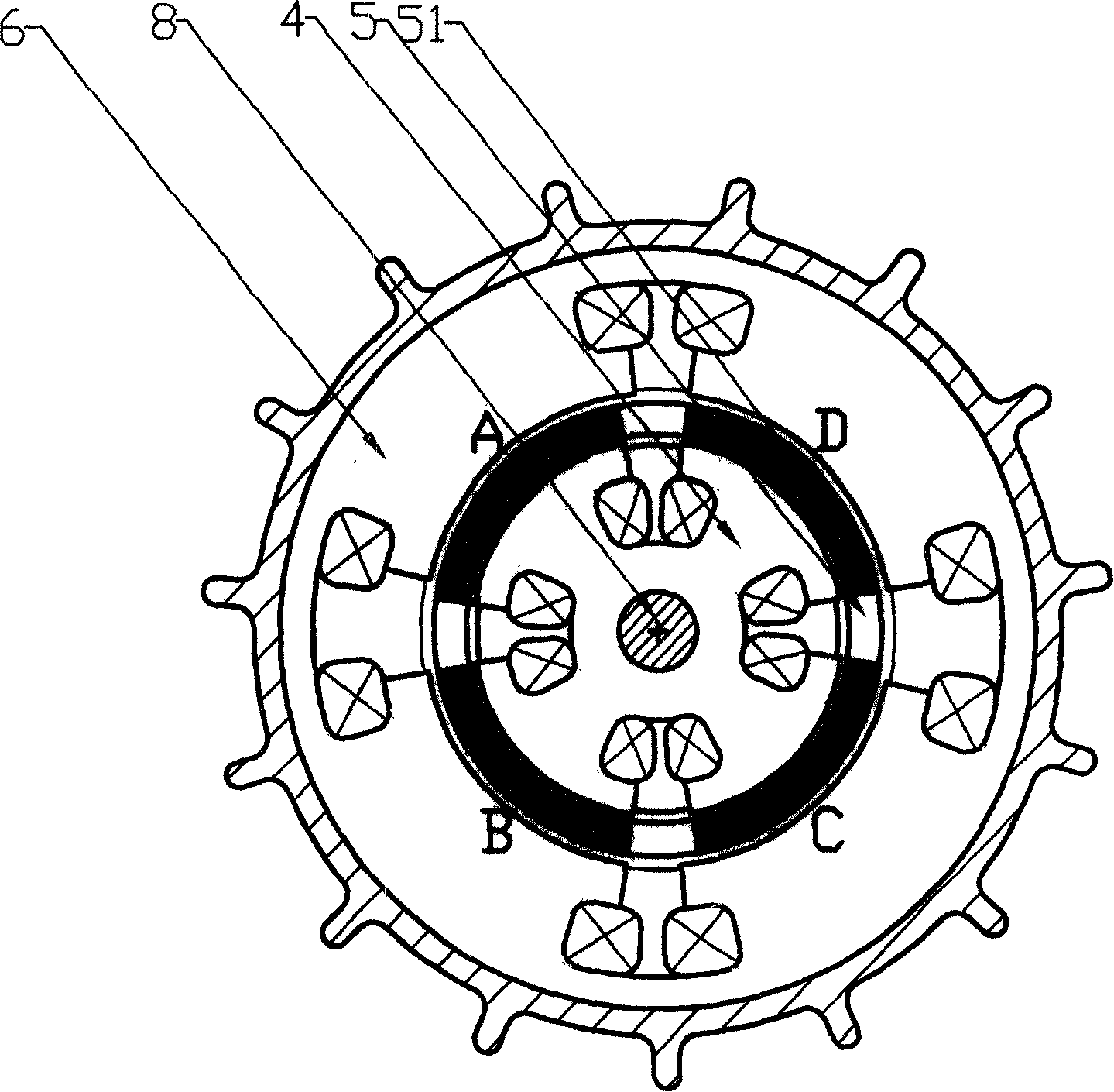
[0020] figure 1 A schematic diagram of the basic structure of the present invention is shown. It includes a control device (9), an energy storage device (10), a power source (1) and a clutch (3), etc., the power source (1) is connected to the electric energy storage transmission through the clutch (3), and the output shaft of the transmission is the drive shaft (8). Below in conjunction with a specific embodiment, the present invention is described in further detail: In the present embodiment, the squirrel-cage magnetic pole group has adopted a permanent magnet four-pole structure, and the power source (1) is realized by a gasoline engine or a diesel engine. figure 2 , image 3 It is an axial sectional view and a radial sectional view of the electric energy storage transmission. One axial end of the squirrel-cage magnetic pole group (5) in the electric energy storage transmission is fixedly connected to the clutch (3), and the squirrel-cage magnetic pole group (5) can rota...


PUM


Abstract

An electrical power storage gear transmission is characterized in that the rotating speed of a power source is no longer corresponding with the on-load rotating speed and the torque linearity, which guarantees the utilizing efficiency of the power resource. The gear transmission can stepless regulation transmission ratio matched with the driving force in accordance with the on-load changes and rotating speed requirements, which accomplishes high stepless speed regulation performance, and has extremely broad speed regulation range and excellent torque output. The gear transmission can operate in a plurality of modes, such as the electrical mode, the driving force source mode and the combination mode, which accomplishes proper distribution of energy source between a driving system and an energy-storage system. The gear transmission reduces the quantity of mechanically driving parts, which lowers the friction loss in the mechanically driving operation effectively; and has simple structure, easy control process and lowered cost.

Description

technical field [0001] An electric energy storage transmission, in particular relates to an electric energy storage transmission used in a drive system of a hybrid vehicle and a method for realizing its function. Background technique [0002] Hybrid drive technology is proposed under the background of improving energy utilization efficiency and reducing pollution emissions to achieve environmental protection. [0003] In the technologies disclosed in Japanese patents 2003-169898 and 2003-169899, ​​in a hybrid vehicle with an engine and a motor, as the engine speed increases, the first control unit gradually increases the power of the motor until the engine speed exceeds the first rotational speed. When the engine speed exceeds the first rotational speed, the first control unit gradually reduces the motor power as the engine speed increases so that the resultant power which is the sum of the engine power and the motor power does not exceed the maximum power of the engine. In...

Claims


Application Information

Patent Timeline
Patent Type & Authority Applications(China)
IPC IPC(8): H02K51/00H02K49/00H02K49/02H02K49/06B60K6/20H02J7/14
Inventor 黄建民
Owner 黄建民
Why Eureka
Try Eureka