
Combustion soaking heavy crude producing technique

A technology of combustion throughput and process technology, which is applied in the field of thermal recovery of heavy oil, can solve problems such as defects and difficulties in the exploitation of combustion oil layers, and achieve the effects of improving production dynamics and reducing viscosity

Inactive Publication Date: 2010-12-08
富象油气技术服务有限公司
View PDF1 Cites 8 Cited by
  • Summary
  • Abstract
  • Description
  • Claims
  • Application Information

AI Technical Summary

Problems solved by technology

[0006] The main purpose of the present invention is to provide a new process technology for heavy oil recovery by incineration huff and puff to overcome the existing difficulties in the production of high-round huff and puff production wells caused by steam huff and puff production or the defects caused by incineration oil layer production

Method used


Image

  • Combustion soaking heavy crude producing technique
  • Combustion soaking heavy crude producing technique

Examples


Embodiment 1

[0036] The buried depth of the oil reservoir in Oilfield 1 is 300-600m, the effective thickness of the oil layer is 36.0m, the net total thickness ratio is 0.7, the average porosity is 28%, the permeability is 700-900md, the underground crude oil viscosity is 800mPa.s, and the oil production capacity before treatment Low, with a water content of 34%.

[0037] 1) Carry out rough screening according to the geological characteristics and development status of the oilfield. The reservoir meets the following conditions:

[0038] Reservoir depth0.5, total thickness of reservoir>6m, reservoir porosity>0.3, permeability>35md, crude oil viscosity<5000mPa.s;

[0039] 2) Use electric heater or natural gas to ignite, the temperature reaches 450°C, after igniting the oil layer, the temperature at the bottom of the well reaches 500°C, and stop the ignition after heating for 20-25°C;

[0040] 3) Inject air into the oil well with an air compressor, and the steam injection intensity reaches ...

Embodiment 2

[0043] Oilfield 2 reservoir is buried at 300-600m in depth, and is developed with an area well pattern similar to the five-point method with a well spacing of 100-150m. There are 14 water injection wells and 17 production wells in total. The volume of the convex lens sand layer in the oilfield is only 128000m 3 The net thickness of the sand layer in the middle of the oilfield is about 6.1m, and there are many shale in the whole sand layer in the form of strips. The porosity of the sand layer is 15-17%, the permeability is 1-80md, the average permeability is about 15md, and the specific gravity of crude oil is 0.859, underground crude oil viscosity 9mPa.s, low oil production capacity before treatment, water content up to 34%. 51,000 tons of crude oil have been produced in the entire oil field before the development of fire huffing and puffing.

[0044] 1) Carry out rough screening according to the geological characteristics and development status of the oilfield. The reservoir ...


PUM


Abstract

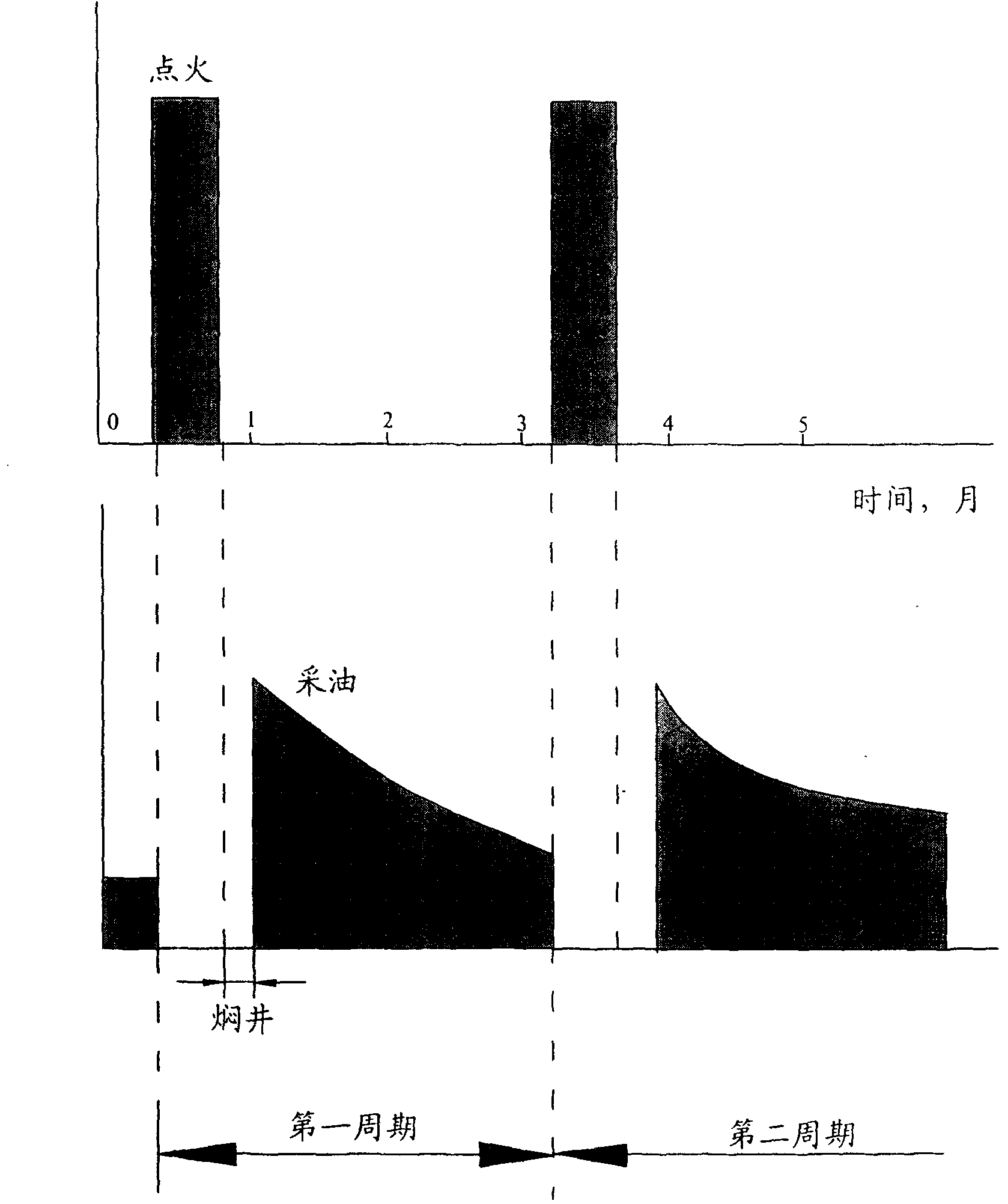
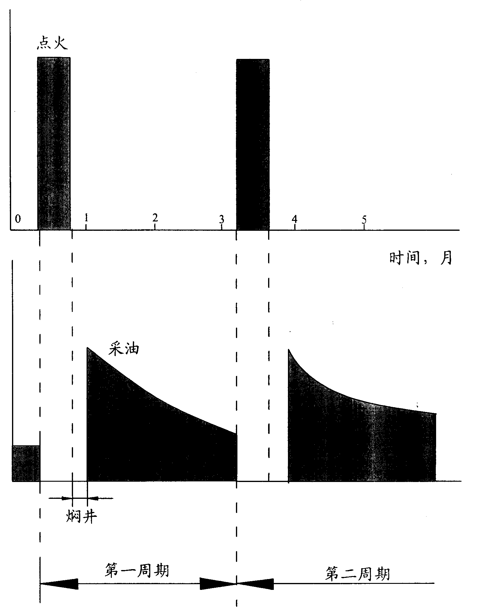
The invention relates to a craftwork technology of pumping thick oil by firing and sorking. The pumping craftwork by firing, sorking is that ignition technologies such as ignition with a radiator, ignition with natural gas or spontaneous ignition are adopted; an oil-well oil layer or a water-well oil layer is heated to have a temperature of over 450 DEG C; the oil well or the water well is continuously injected with oxygen enrichment through an air compressor for 15 to 25 days and ignition is stopped; the oil well or the water well is soaked for 5 to 10 days and opened to be injected with water, thereby reaching the aims of increasing production and injection. The pumping by firing and soaking is mainly used for the pumping of high-turn soaking pumping wells; as the underground storage capacity of the oil well is high and the strata pressure is low, the pumping by firing and soaking can improve daily oil production of per well or moisture pickup of per well to reach the aims of increasing production and injection. The technology is also applicable for oil wells or water wells in which the pumping of steam soaking is not implemented.

Description

technical field [0001] The invention relates to a heavy oil thermal recovery technology, in particular to a technology for heavy oil recovery by fire huffing and puffing. Background technique [0002] In the development of modern oilfields, water injection or gas injection (steam) is generally used to maintain the energy of the oil layer. Because water and gas are relatively easy to inject into the oil layer, and the sources are relatively abundant, they can generally be obtained locally, which is naturally more economical. It is very worthwhile to exchange oil with water or oil with gas. Gas injection generally uses natural gas, CO 2 Or the steam produced by the boiler returns to the oil layer through a special gas injection well. Water injection into the ground can be divided into three types: edge water injection, bottom water injection and internal water injection. Whether it is gas injection or water injection, it must be carried out according to the specific geologi...

Claims


Application Information

Patent Timeline
Patent Type & Authority Patents(China)
IPC IPC(8): E21B43/24F23Q2/00F23Q7/00F23Q13/00
CPCY02E20/34
Inventor 张锐朴晶明邓明
Owner 富象油气技术服务有限公司
Learn More