Resonant vibration dead-soft switching inverter circuit applied to brushless DC motor and control method

A brushed DC motor and inverter circuit technology, applied in the direction of single motor speed/torque control, irreversible DC power input conversion to AC power output, high-efficiency power electronic conversion, etc. The motor can not work normally, increase the conduction power consumption, etc., to achieve the effect of facilitating device selection, overcoming the problem of reverse recovery, and reducing additional costs

Inactive Publication Date: 2008-04-16
NORTHWESTERN POLYTECHNICAL UNIV
View PDF2 Cites 15 Cited by
  • Summary
  • Abstract
  • Description
  • Claims
  • Application Information

AI Technical Summary

Problems solved by technology

Patent 200610105134.5 realizes the soft-switching inverter drive of the brushless DC motor, but the resonant DC link has a power switch located in the main circuit of the DC bus. When any switching tube of the inverter bridge needs to switch, the entire bus voltage must resonate to zero, so that the bus voltage has many zero-voltage grooves, which not only affects the further improvement of the resonant frequency, but also increases the conduction power consumption
Patent 200710017363.6 solves the unfavorable factors brought by the resonant DC link, but the PWM modulation method of the brushless DC motor can only choose HON_LPWM, that is, the switch device on the upper bridge side maintains constant conduction in the 120° interval of conduction, and the switch on the lower bridge side is in conduction The 120° interval works at the PWM modulation frequency. When the power switch of the inverter bridge is driven by a bootstrap circuit, the brushless DC motor will not work normally.

Method used


Image

  • Resonant vibration dead-soft switching inverter circuit applied to brushless DC motor and control method
  • Resonant vibration dead-soft switching inverter circuit applied to brushless DC motor and control method
  • Resonant vibration dead-soft switching inverter circuit applied to brushless DC motor and control method

Examples


Embodiment Construction

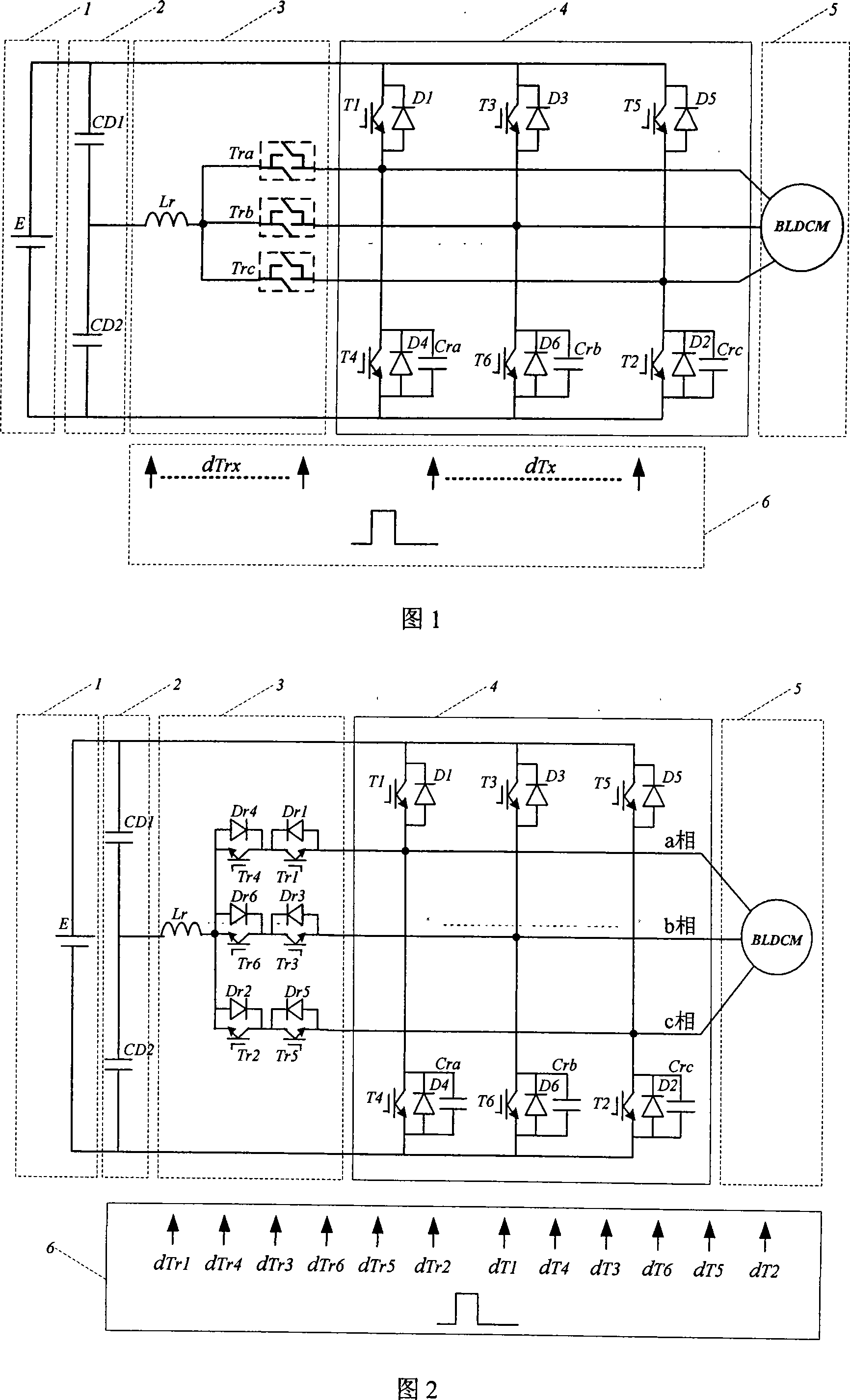
[0040]As shown in Figure 2, the present invention provides a novel resonant extremely soft-switching three-phase inverter applied to brushless DC motors, including: a DC power supply 1, an input voltage divider circuit 2, and a resonant pole auxiliary circuit 3 , a known three-phase inverter bridge 4 and a control circuit 6. The DC power supply 1 adopts the DC power supply E generated by battery series and parallel connection; the input voltage divider circuit 2 is formed by connecting two capacitors CD1 and CD2 in series, and the two ends of the voltage divider circuit 2 are connected to the DC power supply 1; the inverter bridge 4 converts the DC power into AC, each arm of the three-phase inverter bridge is composed of two IGBTs connected in series in the same direction, and each IGBT includes a power switching device Tx and an antiparallel freewheeling diode Dx (x ranges from 1 to 6), and The IGBTs of each lower bridge arm are connected in parallel with buffer capacitors Cr...


PUM


Abstract

The invention discloses a resonance dead-soft switching inverter circuit applied to a brushless DC motor, comprising a DC power supply, an input voltage-dividing circuit, a control circuit and an inverter bridge. The input voltage-dividing circuit comprises two concatenated capacitors; the three poles of the converter bridge are connected to the brushless DC motor. An auxiliary resonance circuit is added between the pole of the converter bridge and the midpoint of the input voltage-dividing circuit, including 3 auxiliary two-way switches and 1 inductometer. One end of each of the 3 auxiliary two-way switches is connected to one end of the inductometer; the other end of each of the 3 auxiliary two-way switches is connected to the pole of a 3-phase converter bridge respectively; the other end of the inductometer is connected to the midpoint of the input voltage-dividing circuit. The control circuit sends out signals to control the auxiliary two-way switches and the converter bridge switching parts to switch on / off. The invention is capable to operate under multiple driving modes.

Description

technical field [0001] The invention relates to a switch conversion circuit and a control method thereof, in particular to a switch inverter circuit and a control method for a brushless DC motor controller. Background technique [0002] Brushless DC motors have achieved rapid development due to their superior performance. However, brushless DC motors are usually driven by hard-switching inverters. The system efficiency of hard-switching inverters is low, and the voltage and current stress of switching devices are large. The volume and weight of the device are relatively large, and the high du / dt and di / dt generated by the hard on / off will bring very serious electromagnetic interference to the system, affecting the insulation life of the motor, and the voltage of the power switching device at the moment of turning on and off And current spikes may make the operating track of the power device exceed the safe operating area, which will cause damage to the power switching device...

Claims


Application Information

Patent Timeline
Patent Type & Authority Applications(China)
IPC IPC(8): H02M7/48H02M7/5387H02P6/08
CPCY02B70/1491Y02B70/10
Inventor 刘卫国贺虎成
Owner NORTHWESTERN POLYTECHNICAL UNIV
Why Eureka
Try Eureka