
Dry film, micro-lens and manufacturing method thereof

A technology of microlens and dry film, which is applied in the photographic process of patterned surface, photosensitive material for optomechanical equipment, optics, etc. It can solve the problem of insufficient lens strength and solvent resistance, and lens shape defects, which have not been proposed. And other issues

Inactive Publication Date: 2008-04-23
JSR CORPORATIOON
View PDF5 Cites 9 Cited by
  • Summary
  • Abstract
  • Description
  • Claims
  • Application Information

AI Technical Summary

Problems solved by technology

[0005] However, it has been known that when the conventionally known radiation-sensitive resin composition for forming a microlens is directly used in the dry film method, the lens strength and solvent resistance required for the microlens tend to be insufficient.
That is to say, in order to obtain microlenses with excellent strength and solvent resistance, it is generally better to use hard materials, but the composition that is suitable for obtaining a hard coating in the dry film method has the possibility of curing the composition during storage. situation, therefore, is believed to place limitations on the hardness of the material that can be applied
Therefore, it is believed that it is difficult to improve the performance of the above-mentioned microlenses when using the dry film method.
[0006] Furthermore, it is also known that the microlens formed by the dry film method has poor surface smoothness due to the radiation-sensitive resin composition layer transferred onto the substrate, thus causing defects in the shape of the lens, or deteriorating the resolution and light collection of the microlens. Sex is not enough
[0007] Therefore, there is a strong demand for a method for forming high-definition microlenses by simply adopting a dry film method, which is beneficial to industrial applications, with a high product yield, but a method that satisfies such requirements has not yet been proposed.

Method used


Image

  • Dry film, micro-lens and manufacturing method thereof
  • Dry film, micro-lens and manufacturing method thereof
  • Dry film, micro-lens and manufacturing method thereof

Examples


Embodiment

[0307] The following examples and comparative examples are used to further specifically explain the present invention, but the present invention is not limited to the following examples.

[0308] The three-dimensional ten-point average roughness SRz and the three-dimensional maximum height SRmax of each base film were evaluated with a white interference microscope "New View 5032" (produced by ZYGO).

[0309] The adhesion of the cover film was evaluated by crimping a 50 mm wide sample on a PMMA plate at room temperature (23° C.) with a pressure of 0.45 MPa, and then performing state adjustment at room temperature for 20 minutes, and then performing a peel test.

[0310]

Synthetic example 1

[0312] After replacing the flask with nitrogen, 3 g of a radical polymerization initiator 2,2'-azobisisobutyronitrile and 100 g of methyl 3-methoxypropionate as a solvent were added and stirred until the radical polymerization initiator was dissolved until. Then, add 19g of methacrylic acid, 15g of 2-mono(hexahydrophthaloyloxy)ethyl methacrylate, 15g of styrene and 46g of tricyclodecyl methacrylate, slowly start stirring, and add further 5g isoprene. Then, the temperature of the reaction solution was raised to 80°C and polymerized at this temperature for 4 hours to obtain 2-(hexahydrophthaloyloxy)ethyl methacrylic acid / methacrylic acid / styrene / formaldehyde Tricyclodecyl acrylate / isoprene copolymer (copolymer weight ratio = 19 / 15 / 15 / 46 / 5, M w = 13,000, M n =8,000) copolymer solution. The copolymer contained in this copolymer solution is referred to as copolymer (A-1).

Synthetic example 2

[0314] Except for changing the type and amount of the unsaturated compound, the polymerization reaction was carried out in the same manner as in Synthesis Example 1, and the obtained product contained methacrylic acid / styrene / benzyl methacrylate / glyceryl monomethacrylate / N-phenyl Lyimide copolymer (copolymer weight ratio = 15 / 15 / 35 / 10 / 25, M w =7,000, M n =4,000) copolymer solution. The copolymer contained in this copolymer solution is referred to as copolymer (A-2).


PUM

PropertyMeasurementUnit
thicknessaaaaaaaaaa
thicknessaaaaaaaaaa
mean roughnessaaaaaaaaaa

Abstract

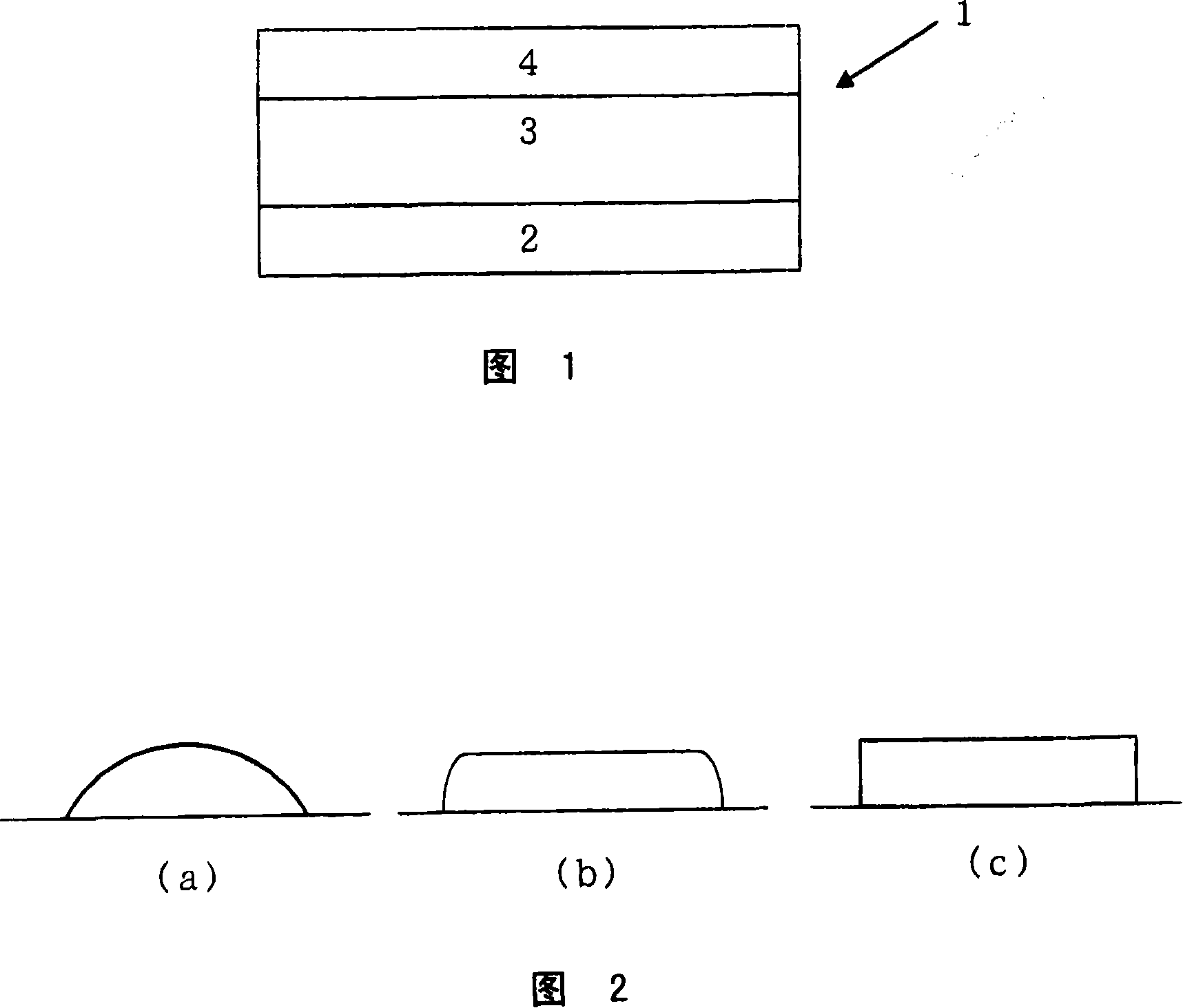
The present invention relates to dry film, microlens and the preparing method thereof. Said dry film contains (I) the basilar membrane having a surface with the three-dimensional ten-point average roughness SRz below 2.2 mum and the three-dimensional maximum height SRmax the same as 4.0 mum and a thickness from 10 mum to 50 mum; (II) the radioactive ray sensibility resin composition layer with the thickness from 2mum to 200mum laminated on the surface of said basilar membrane (I); and (III) the cover membrane covering said radioactive ray sensibility resin composition layer (II).

Description

Technical field [0001] The present invention relates to dry films, microlenses, their manufacturing methods, and liquid crystal display elements having microlenses. Background technique [0002] Among the display elements, especially liquid crystal display elements, they have been found in flat panel displays for their excellent characteristics such as low power consumption, high reliability, flexibility to handle wide sizes, high precision and color display characteristics, thinness and light weight. The most widely used applications, however, with the popularity of office automation (OA) equipment such as personal computers and word processors, LCD TVs, mobile phones, projectors, etc., the performance requirements have become more and more stringent in recent years. In response to these requirements, JP 2003-255318, 2001-154181, 2001-117114, JP 11-109417, and JP 10-268305 have already been proposed A method of improving the brightness and contrast of the liquid crystal display ...

Claims


Application Information

Patent Timeline
Patent Type & Authority Applications(China)
IPC IPC(8): G03F7/004G03F7/027G03F7/028G03F7/00
Inventor 吉田伸石川真义林明弘饭田雅史
Owner JSR CORPORATIOON
Learn More