

Making technology method for flash memory
A manufacturing process and flash memory technology, which is applied in the field of semiconductor integrated circuit technology to achieve the effects of small impact, improved erasing and writing performance, and favorable subsequent processes
- Summary
- Abstract
- Description
- Claims
- Application Information
AI Technical Summary
Problems solved by technology
Method used
Image

Examples
Embodiment Construction
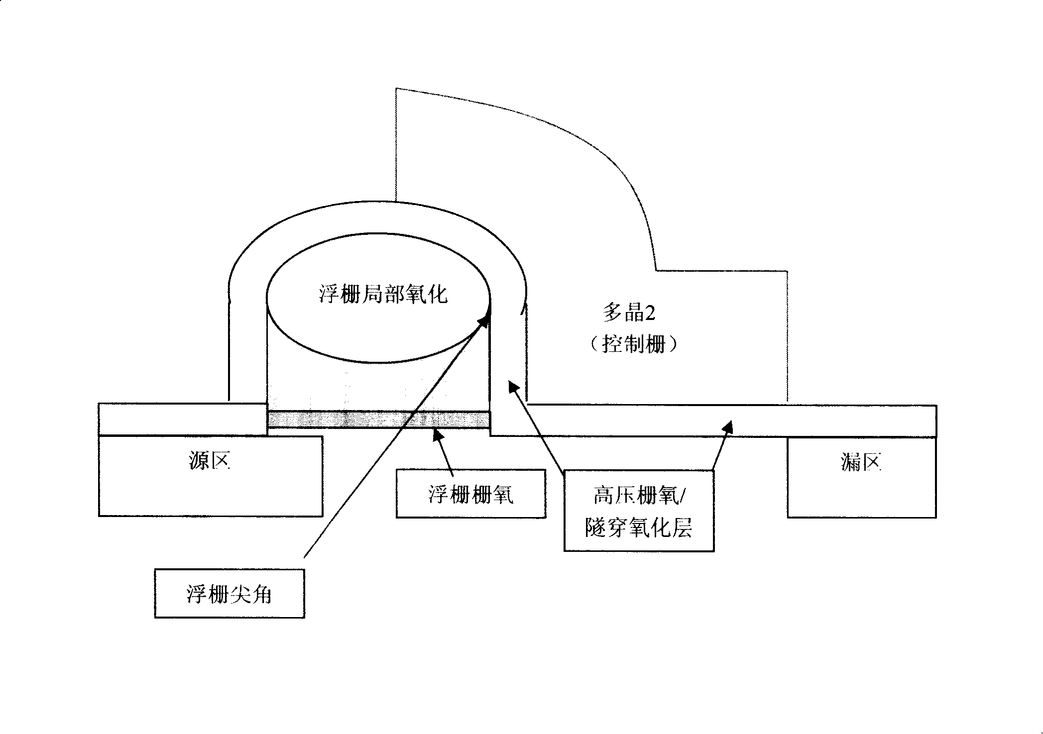
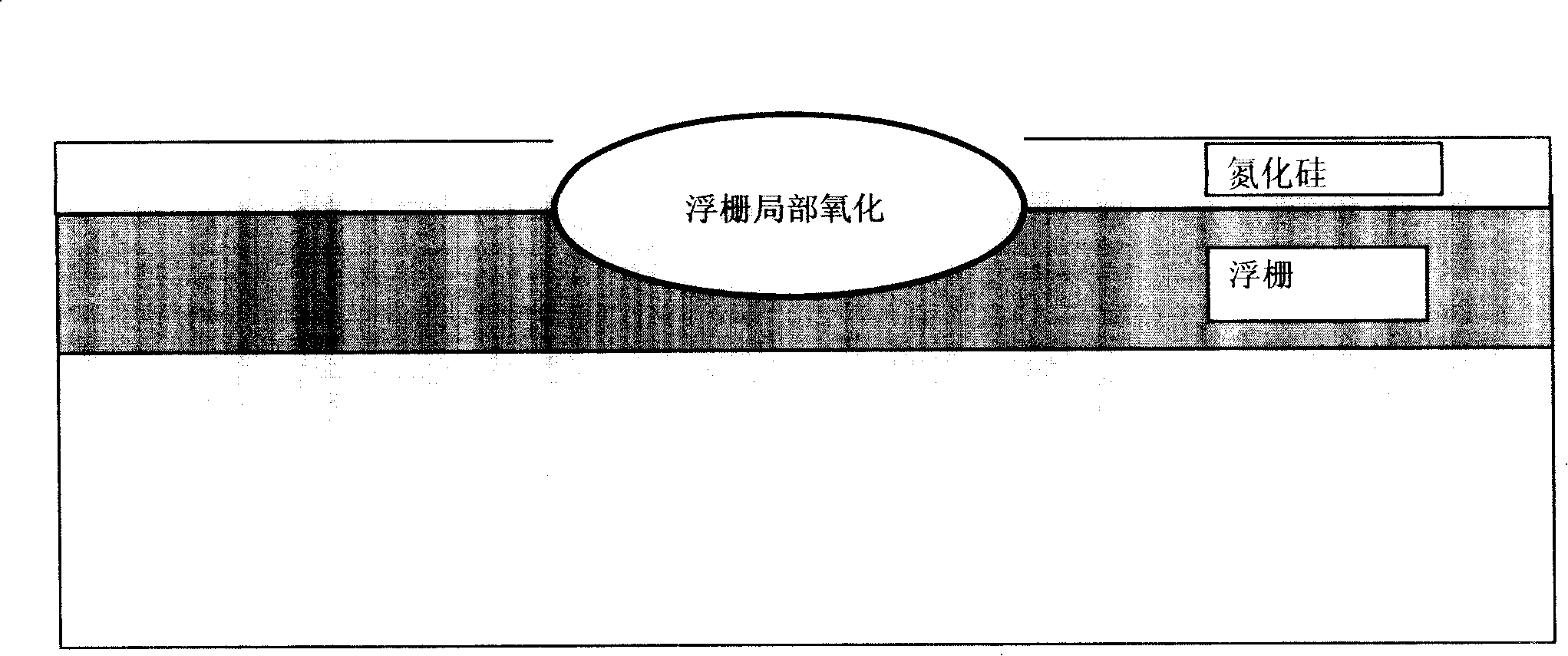
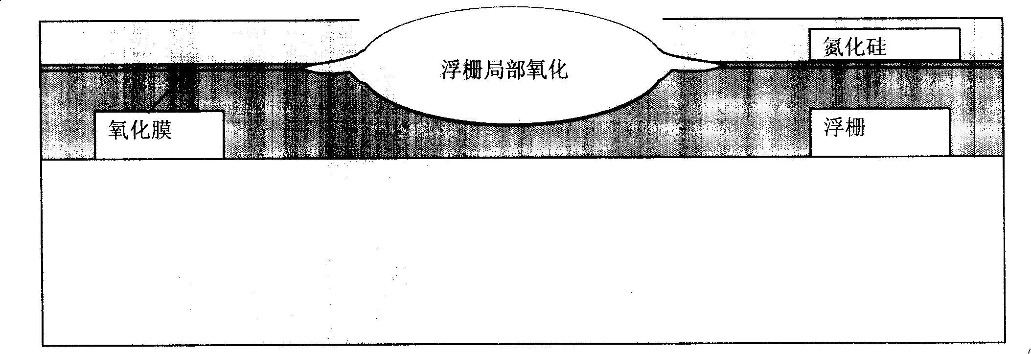
[0015] The main process steps that the present invention adopts are as follows: 1. isolation region / active area forms (same as existing technology); 2. high-voltage transistor, memory cell well implantation (same as existing technology); 3. floating gate oxidation (same as existing technology); Crafted, 85 ); 4. Floating gate polycrystalline deposition (with existing technology, 1100 ); 5. A thin layer of oxide film is grown on the surface of the floating gate for about 20 to 50 6. Silicon nitride deposition; 7. Partial oxidation of the floating gate (same as the existing process); 8. Etching of the floating gate (same as the existing process); 9. The subsequent steps are also the same as the existing process.
[0016] The present invention is compared with the existing technology: steps 1-4 are the same as the existing technology, after the floating gate is oxidized, a layer of polysilicon is deposited on the surface; a process procedure is added afterwards, that is, a la...
PUM
 Abstract
Description
Claims
Application Information