Method for processing and recycling drill cuttings

A recovery method and drilling cuttings technology, applied in the field of drilling waste treatment and recovery, can solve the problems of unrecoverable oil base, small amount of waste treatment, high operating cost, etc., to achieve reduced disposal costs, large amount of treatment, and low operating cost Effect

Inactive Publication Date: 2008-05-07
CHINA NAT OFFSHORE OIL CORP +3
View PDF0 Cites 18 Cited by
  • Summary
  • Abstract
  • Description
  • Claims
  • Application Information

AI Technical Summary

Problems solved by technology

However, these methods have high operating costs, small amount of waste treatment, low efficiency, and the oil base cannot be recycled

Method used


Image

  • Method for processing and recycling drill cuttings

Examples


Embodiment 1

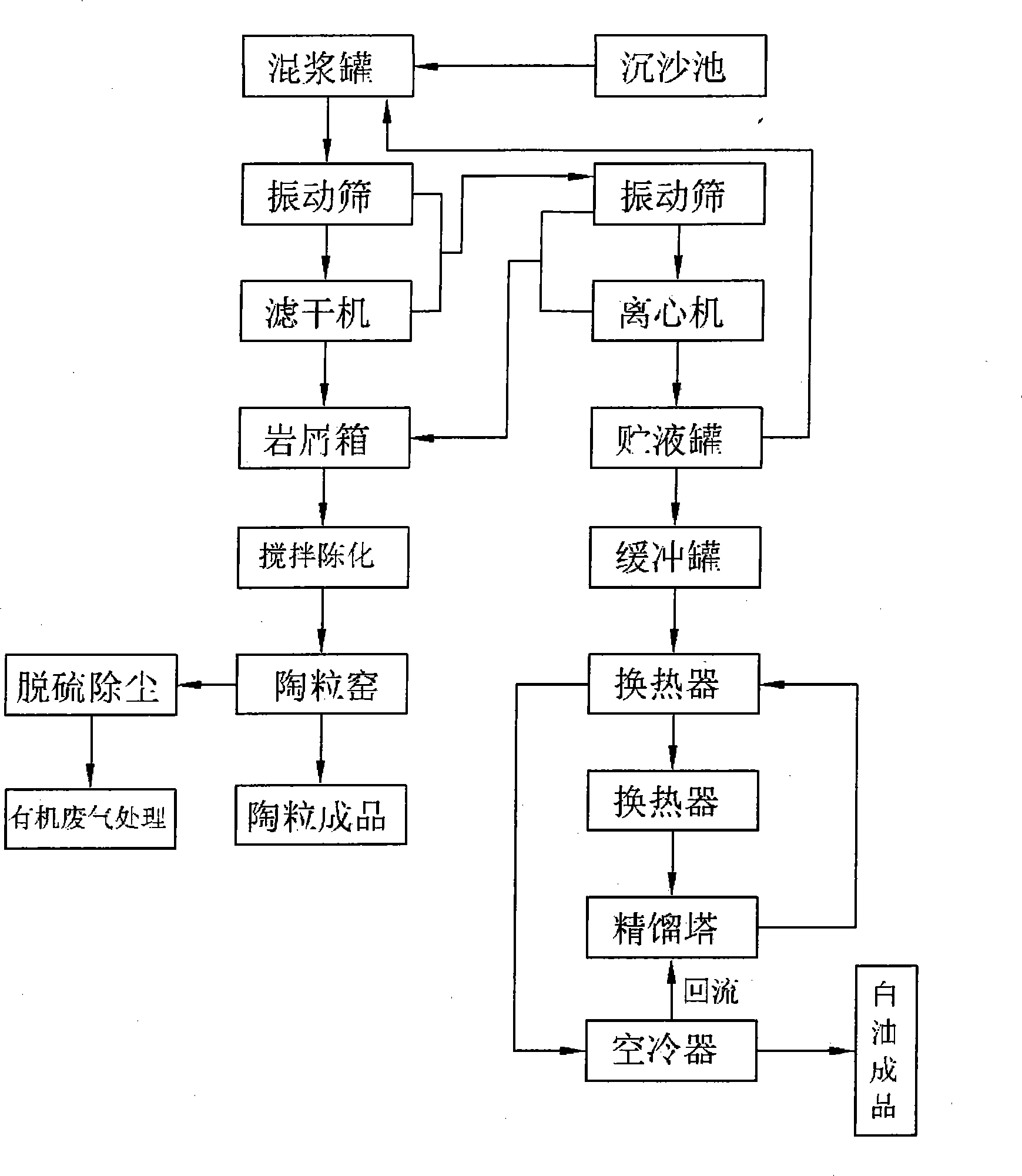
[0020] Inject the oil-based drilling cuttings back to the shore into the grit chamber; pump the drill cuttings in the grit chamber into the mixing tank, and adjust the liquid-solid ratio in the mixing tank to be 4:1 by weight percentage; The mixed slurry in the mixing tank is pumped into the first vibrating screen for screening, wherein the concentration of the oversize is kept at 30% in weight percentage, and the mesh of the vibrating screen is 100 mesh; the first vibrating The undersize of the sieve freely falls into the filter dryer to filter dry, and the dried solid phase is sent to the screw conveyor to be transported to the salt dust box. The filter mesh of the filter dryer is 0.8mm; The undersize of a vibrating screen is combined with the overflow of the filter dryer and sent to the second vibrating screen; the oversize of the second vibrating screen falls into the screw conveyor and is transported to the salt dust box, and the undersize is Pumped into the centrifuge th...

Embodiment 2

[0022] Inject the oil-based drilling cuttings back to the shore into the grit chamber; pump the drill cuttings in the grit chamber into the mixing tank, and adjust the liquid-solid ratio in the mixing tank to be 6:1 by weight percentage; The mixed slurry in the mixed slurry tank is pumped into the first vibrating screen for screening, wherein the concentration of the oversize is maintained at 60% in weight percentage, and the mesh of the vibrating screen is 150 mesh; the first vibrating The undersize of the sieve freely falls into the filter dryer to filter dry, and the solid phase after the filter is sent to the screw conveyor to be transported to the salt dust box. The filter screen mesh gap of the filter dryer is 1.0mm; The undersize of a vibrating screen is combined with the overflow of the filter dryer and sent to the second vibrating screen; the oversize of the second vibrating screen falls into the screw conveyor and is transported to the salt dust box, and the undersize...

Embodiment 3

[0024]Inject the oil-based drilling cuttings back to the shore into the grit chamber; pump the drill cuttings in the grit chamber into the mixing tank, and adjust the liquid-solid ratio in the mixing tank to be 8:1 by weight percentage; The mixed slurry in the mixing tank is pumped into the first vibrating screen for screening, wherein the concentration of the oversize is kept at 20% in weight percentage, and the mesh of the vibrating screen is 80 mesh; the first vibrating The undersize of the sieve freely falls into the filter dryer to filter dry, and the dried solid phase is sent to the screw conveyor to be transported to the salt dust box. The filter screen mesh gap of the filter dryer is 0.4mm; The undersize of a vibrating screen is combined with the overflow of the filter dryer and sent to the second vibrating screen; the oversize of the second vibrating screen falls into the screw conveyor and is transported to the salt dust box, and the undersize is Pumped into the cent...


PUM


Abstract

The invention discloses a processing and recovery method of a drill chip. The method comprises the following steps: the drill chip in a settling basin is pumped into a slurry mixing tank; mixed slurry in the slurry mixing tank is pumped into a first vibratory screen to be screened; screenings of the first vibratory screen freely falls into a filtering dryer to perform filtering and drying, solid phase after being filtered and dried is sent to a screw conveyer to be conveyed to a salt chip box; the screenings of the first vibratory screen and the flowing of the filtering dryer are mixed and conveyed into a second vibratory screen; the screenings of the second vibratory screen falls into the screw conveyer to be conveyed to the salt chip box, the screenings is pumped into a centrifugal machine through a pump; solid phase separated by the centrifugal machine enters into the screw conveyer to be conveyed to the salt chip box, liquid phase enters into a liquid storage tank to be produced into a white oil product; the drill chip in a salt chip box and clay are mixed and produced into haydite. The method of the invention is to recovery oil base in the drill chip, building materials manufactured by rock chip slurry reduce the cost expense, compared with the prior art, the running cost is low, the processing rate is large, and the efficiency is high.

Description

technical field [0001] The invention relates to a method for processing and recycling drilling waste, in particular to a method for processing and recycling drilling cuttings. Background technique [0002] Drill cuttings mainly refer to formation cuttings that are destroyed during drilling and carried back to the ground through mud circulation. The main substances that drill cuttings pollute the marine environment are mud and oil substances mixed with drill cuttings. [0003] Drilling cuttings contamination due to toxic components in the composition of drilling fluids can have a devastating effect. Despite the use of some special separation and cleaning equipment, cuttings still contain a range of organic and inorganic components, especially when oil-based drilling fluids are used. Drill cuttings are usually discharged into the sea from the drilling platform in thousands or tens of thousands of tons. Hundreds of tons of oil and dozens of tons of chemicals per well drilled ...

Claims


Application Information

Patent Timeline
Patent Type & Authority Applications(China)
IPC IPC(8): B09B5/00B09B3/00
Inventor 邬灿金张辉刘长荣程秀刘键毕炎超
Owner CHINA NAT OFFSHORE OIL CORP
Why Eureka
Try Eureka