
Method for processing container with deep wall

A processing method and technology for deep-wall containers, which are applied in the field of plastic processing, can solve the problems of large power consumption, large processing cycle and high processing cost, and achieve the effects of reducing occupied space, good sealing performance and high edge strength.

Inactive Publication Date: 2008-05-07
NANJING HONGJU PLASTIC STEEL PRODS
View PDF0 Cites 7 Cited by
  • Summary
  • Abstract
  • Description
  • Claims
  • Application Information

AI Technical Summary

Problems solved by technology

But it also has its shortcomings: empty barrels and solid barrels occupy the same space, which makes the transportation cost high, and companies using this type of container need a huge space; in addition, the inner wall of the container is naturally solidified, and its inner wall roughness is large Containing viscous materials, there is a serious "wall hanging" phenomenon
However, solidification and shaping are relatively difficult. The larger the product area, the longer the cooling time, and the longer the processing cycle (about 3 minutes per mold for general products, and 30 minutes or longer for thermal model cores and mold cavities). Larger power consumption and processing costs It is very high, so the products produced by this method cannot be accepted by the market
[0015] 3. Multi-point feeding: Traditional multi-point feeding, usually hot runner feeding on the same plane, is difficult to form for deep-walled containers (container height H / bottom diameter φ>1, volume V>25L)

Method used


Image

  • Method for processing container with deep wall
  • Method for processing container with deep wall
  • Method for processing container with deep wall

Examples


Embodiment Construction

[0044] Below in conjunction with accompanying drawing, the present invention is specifically introduced as follows:

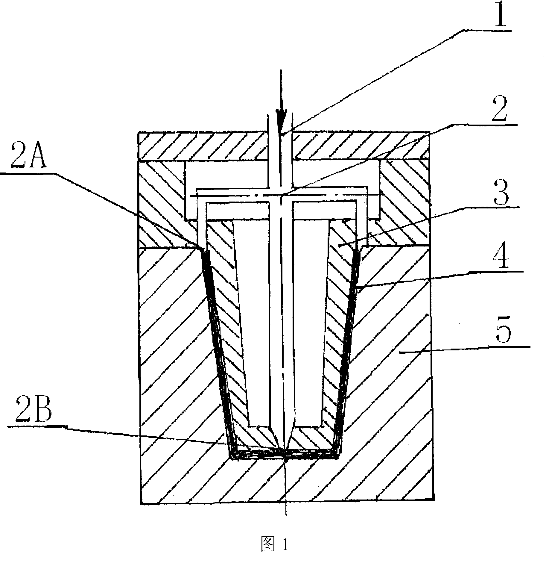
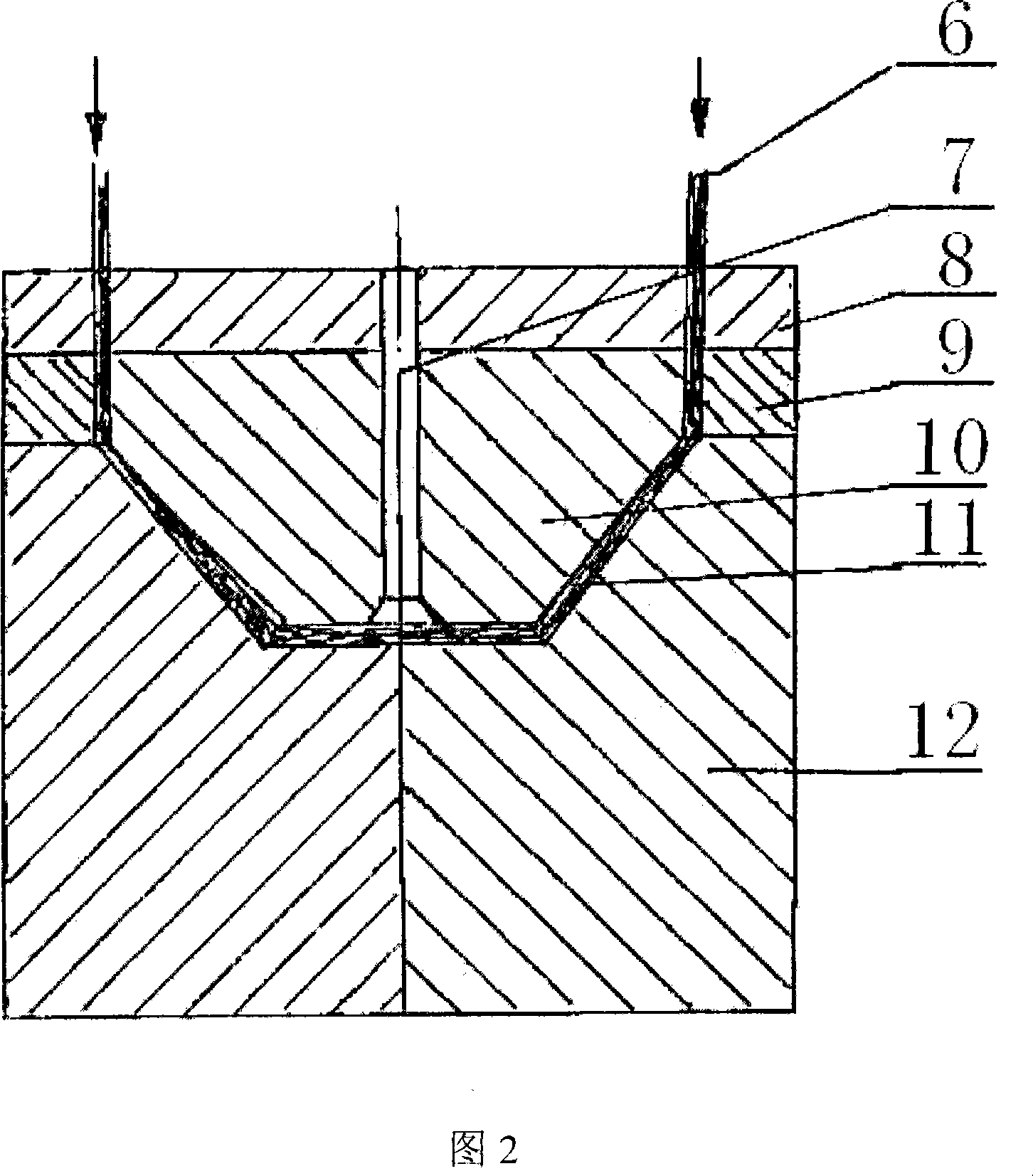
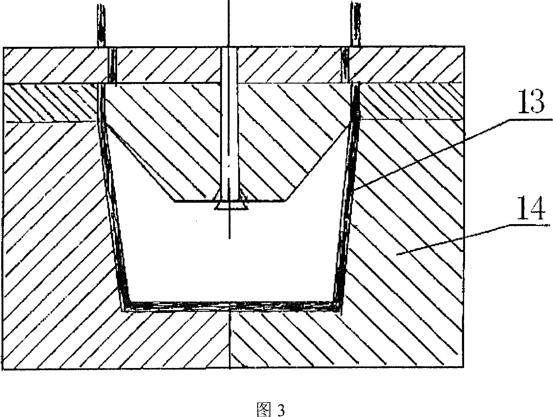
[0045] Fig. 1 is a schematic diagram of the injection molding processing method in the present invention. As shown in the figure, when the weight of the product is less than 4kg, the one-time injection molding method of the three-dimensional feeding port can be selected. Features of mold feeding structure: Design a group of feeding ports perpendicular to the axis of the screw, and the materials at each layer of feeding points go towards each other to complete the materials that need to be filled on the side walls. In order to ensure filling, at least one feed point is designed on the bottom of the inner wall of the container, and at least two feed points are designed on the edge of the mouth, and the filling of the cavity is completed at each point during the injection process. Assuming that the maximum injectable volume of each feed point is Vn (n ∈ natural n...


PUM

PropertyMeasurementUnit
Melt indexaaaaaaaaaa

Abstract

The invention relates to a processing method of a deep wall container, the method comprises the following steps: a die assembly is arranged and clamped on an injection mold machine, to lead the sprue mouth of the injection mold machine to being oppositely connected with the feeding hole of the die assembly, and to form a closed fluid channel; a solid granular or powder raw material is warmed up to a molten status, under the rotating and extruding function of a threaded rod, the raw material is pressed into the feeding hole of the die assembly through the sprue mouth; the raw material enters and fills up a cavity through the fluid channel; a product is formed through dwelling, cooling and solidifying, and then the product is taken out by opening the fluid channel. The invention is characterized in that the raw material is HDPE material with melt index less than 2.0g / 10 min; at least two feed points are arranged on the mouth edge of the container of the fluid channel, and a feeding hole is arranged on the inner wall bottom face of the container. The invention can lead the material with melt index less than 2.0g / 10 min which can not be used for injection mold and processing to be used for processing a plastic product, and enable the material performance to be good, the service life to being long, the mouth edge strength to be high, the impact strength to be high, and the sealing property to be good.

Description

technical field [0001] The invention relates to a processing method of a hollow plastic container, in particular to a processing method of an HDPE deep-wall container which can be used on an ordinary injection molding machine and is applicable to a melt flow rate of less than 2.0g / 10min, and belongs to the plastic processing technology field. Background technique [0002] The melt flow rate, or melt index (MI), refers to the quality of the melt of a thermoplastic resin passing through a standard capillary within 10 minutes at a certain temperature and load. (For polyethylene, the temperature is 190° and the load is 21.17N). [0003] HDPE stands for low-pressure high-density polyethylene. The HDPE material itself has good chemical stability and has corrosion resistance to acids, alkalis and salt water melts. Its melt index (MI) is inversely proportional to molecular weight, the larger the molecular weight, the smaller the melt index; the smaller the molecular weight, the la...

Claims


Application Information

Patent Timeline
IPC IPC(8): B29C45/27B29C45/47B29C49/06B29C49/50B29C49/48B29C49/42B29K23/00B29L22/00
Inventor 周红年
Owner NANJING HONGJU PLASTIC STEEL PRODS
Learn More