Digital camera

A digital camera and functional technology, which is applied in the field of digital cameras, can solve the problems of different brightness levels of subjects and no uniform benchmark of brightness signal levels, etc., and achieve the effect of maintaining fineness and improving recognition

Inactive Publication Date: 2008-05-07
PANASONIC CORP
View PDF2 Cites 10 Cited by
  • Summary
  • Abstract
  • Description
  • Claims
  • Application Information

AI Technical Summary

Problems solved by technology

[0009] In the prior art, appropriate exposure control and aperture control are performed according to the shooting conditions. However, since there is no uniform standard for the level of the brightness signal of the subject, the brightness of the subject varies with the shooting conditions.

Method used


Image

  • Digital camera
  • Digital camera
  • Digital camera

Examples


no. 1 example

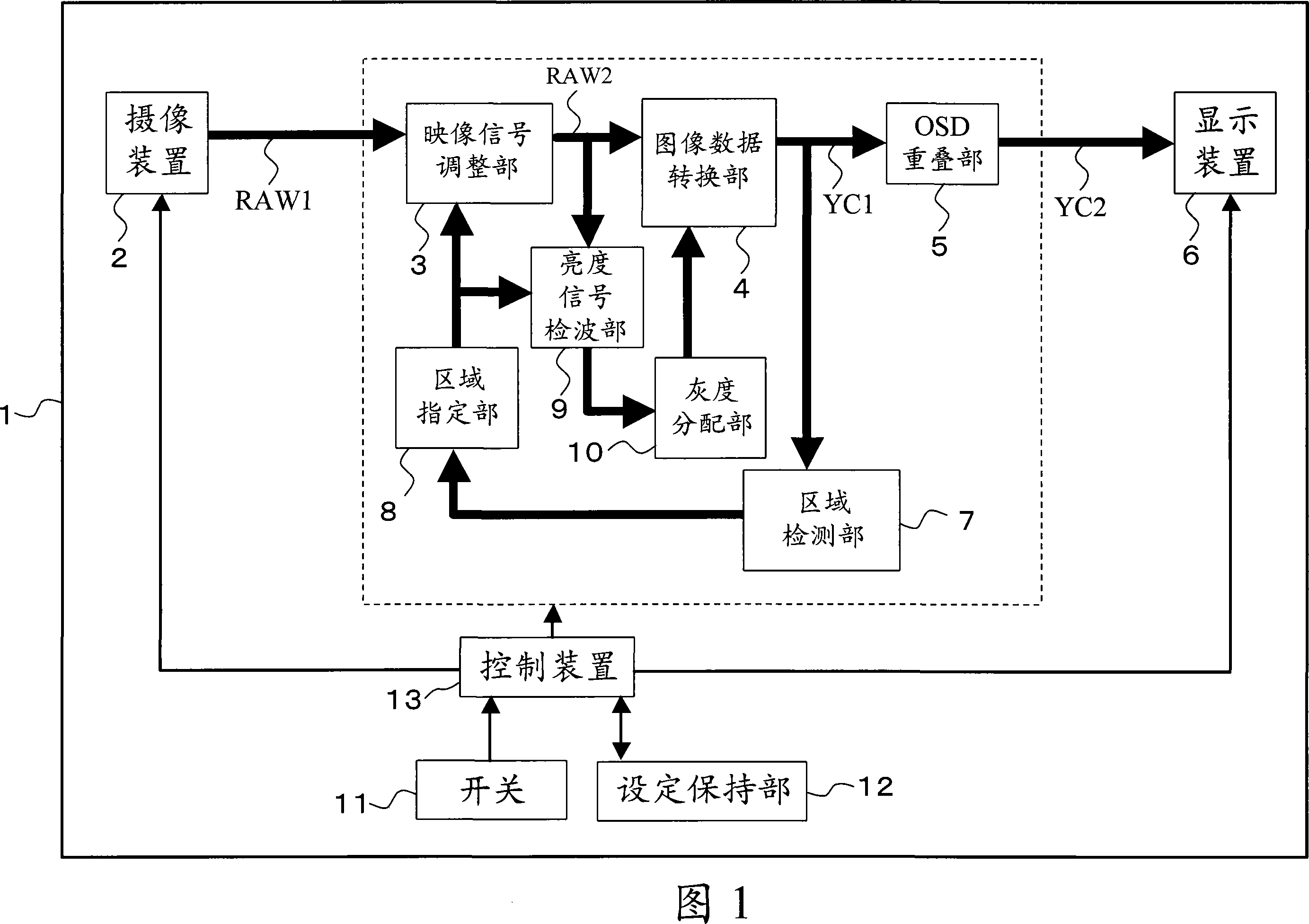
[0037] The configuration of the digital camera of the first embodiment is shown in FIG. 1 . This digital camera 1 includes: an imaging device 2, an image signal adjustment unit 3, an image data conversion unit 4, an on-screen video control system superimposition unit 5, a display device 6, an area detection unit 7, an area designation unit 8, and a brightness signal detection unit 9 , a gradation distribution unit 10, a switch 11, a setting holding unit 12, and a control device 13.

[0038] The imaging device 2 converts light from a subject into an image signal RAW1 corresponding to R·G·B by a solid-state image sensor such as a CCD or a CMOS, and outputs the image signal RAW1. The video signal adjustment unit 3 performs individual gain adjustment of various color components (R·G·B) of the video signal RAW1 from the imaging device 2, white balance adjustment, offset addition, and defect correction etc., and output as the adjusted image signal RAW2. The image data converting u...

no. 2 approach

[0048] The configuration of the digital camera of the second embodiment is shown in FIG. 14 . This digital camera 1 further includes an automatic exposure (AF=Auto-Focus) control unit 20 in addition to the components shown in FIG. 1 . The automatic exposure control unit 20 performs control to focus on a subject. Fig. 15 shows images and correction areas in the digital camera 1 of the present embodiment.

[0049] Usually, when performing auto-focus control, there are several auto-focus areas (Auto-Focus areas) to focus on. In this case, the seven quadrangular ranges (Auto-Focus ranges) in FIG. 15(a) correspond to auto-focus areas. Here, if the auto-focus area is selected as the specified area, as shown in FIG. 15( b ), the image in the focused auto-focus area is corrected as the correction target area. Since the focus is generally on the desired area of ​​the subject, as long as the AF area is designated as the designated area, the trouble of specifying the correction target...

no. 3 approach

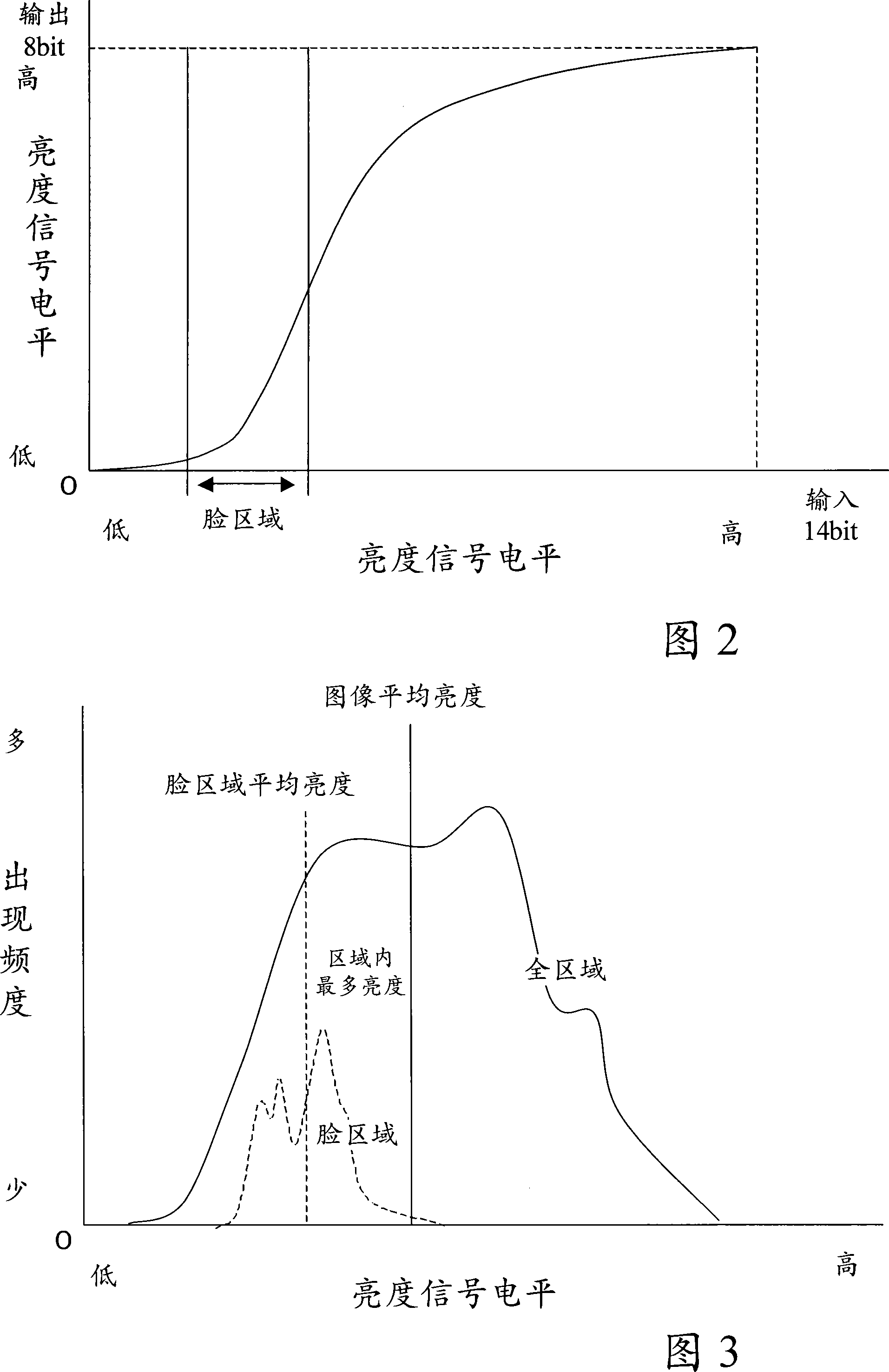
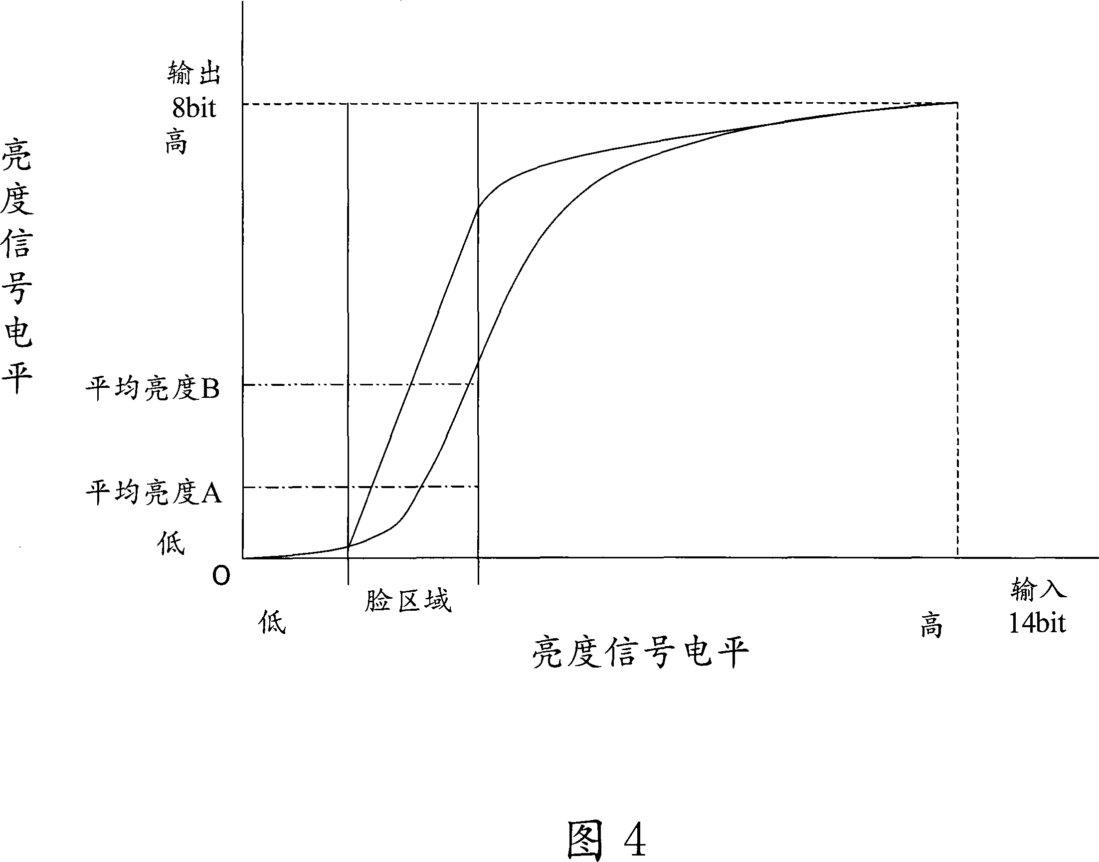
[0051] The configuration of the digital camera of the third embodiment is shown in FIG. 16 . This digital camera 1 includes, in addition to the components shown in FIG. 1 , a memory device 30 for storing video signals and the like, and a memory access unit 31 for storing / retrieving video signals in the memory device 30 . Furthermore, the image data conversion unit 4 converts the video signal from the memory access unit 31 into image data. The control device 13 controls each processing unit that generates image data from the video signal repeatedly until the luminance signal (average luminance, maximum luminance, minimum luminance) of the area specified by the area specifying unit 8 reaches a predetermined value.


PUM


Abstract

A digital camera including: an imaging device having a function to control a quantity of transmitted light of an imaging optical system and a function to subject the transmitted light to photoelectric conversion to generate a video signal; an area specifying portion specifying an area to control; an image data conversion portion converting the video signal generated by the imaging device to image data including a luminance signal and a color difference signal and outputting the image data; a luminance signal detection portion detecting the luminance signal from the video signal or the image data; a gradation assignment portion giving an instruction to the image data conversion portion on assignment of gradation based on information detected by the luminance signal detection portion; and a control device controlling the imaging device, the area specifying portion, the gradation assignment portion, the image data conversion portion, and the luminance signal detection portion. The image data conversion portion performs the conversion based on the instruction on assignment of gradation from the gradation assignment portion.

Description

technical field [0001] The present invention relates to a digital camera including a solid-state imaging device (CCD, CMOS, etc.) having a photoelectric conversion function. Background technique [0002] In recent years, with the popularization of digital cameras (digital conventional cameras, digital video cameras, camcorders, etc.), digitization of photo images has become easier, and opportunities to process photo-adjusted images as digital image data on personal computers have increased. [0003] In addition, with the spread of application software capable of correcting and processing images, users can freely perform image processing on personal computers. For example, processing for correcting a relatively dark image to brighten it, processing for making wrinkles less conspicuous by adding LPF to skin color parts, and the like can be mentioned. [0004] Against such a background, in photography, an image processing technology that is feasible without image correction or...

Claims


Application Information

Patent Timeline
Patent Type & Authority Applications(China)
IPC IPC(8): H04N5/225H04N5/232
CPCG06T2207/20012G06T2207/10016G06T5/001H04N5/23293G06T2207/30201H04N5/235G06T5/008H04N5/23212G06T2207/10024H04N23/611H04N23/70
Inventor 荒川贤治
Owner PANASONIC CORP
Why Eureka
Try Eureka