Compound shade ultra-distinguish differential confocal measurement method and device

A differential confocal, measuring device technology, applied in the field of ultra-precision measurement, can solve the problems of only applicable, narrow, small linear measurement range, etc., to achieve the effect of improving the signal-to-noise ratio, suppressing common mode noise, and extending the linear range

Active Publication Date: 2008-05-21
哈尔滨超精密装备工程技术中心有限公司
View PDF0 Cites 40 Cited by
  • Summary
  • Abstract
  • Description
  • Claims
  • Application Information

AI Technical Summary

Problems solved by technology

Its basic idea was proposed by M.Minsky in 1957 and obtained a U.S. patent in 1961. Its basic technical idea is to suppress stray light by introducing a pinhole detector and generate axial tomography capabilities. The reason is that the measurement sensitivity of the axial response signal is not high near the quasi-focus area of ​​the measurement surface, so it is only suitable for defocus displacement measurement
[0006] Attached Figure 2 is a typical wavelength response curve of the above-mentioned system, as shown in the figure, its linear measurement range is AX, and the measurement origin is O1, that is, when the position of the measurement surface moves from A to position X, differential motion can be effectively performed Or super-resolution differential confocal measurement, however, in this system, the high axial measurement resolution obtained by using a large numerical aperture focusing objective lens is contradictory to the extension of the axial measurement range, that is, the higher the axial resolution , the smaller the linear measurement range, this relatively narrow linear measurement range is one of the main obstacles restricting the wider application of existing differential and super-resolution differential confocal measurement techniques

Method used


Image

  • Compound shade ultra-distinguish differential confocal measurement method and device
  • Compound shade ultra-distinguish differential confocal measurement method and device
  • Compound shade ultra-distinguish differential confocal measurement method and device

Examples


Embodiment Construction

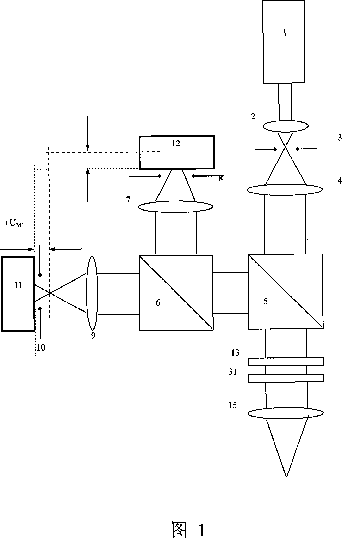
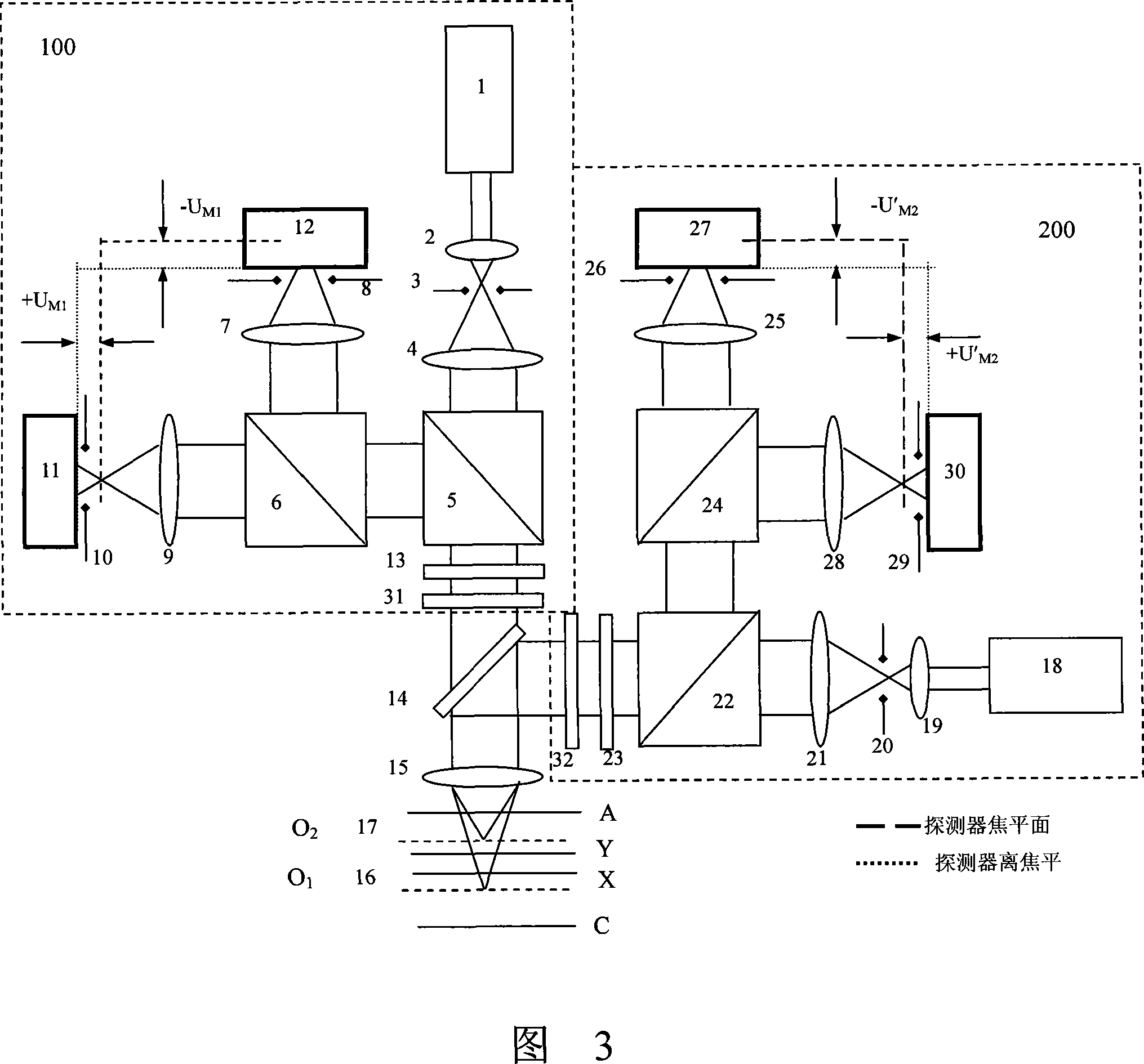
[0022] Referring to FIG. 3 , the polychromatic super-resolution differential confocal measurement device provided in the first specific embodiment of the present invention includes a first super-resolution differential confocal measurement device 100, and the first super-resolution differential confocal measurement device 100 Including the first laser 1, the first laser emits the first wavelength λ 1 The light of the first wavelength is collimated through the first collimating and focusing objective lens 2, the first pinhole 3 and the first collimating and focusing objective lens 4, and then divided into two beams of polarized light by the first polarizing beam splitter 5, One beam of polarized light is split by the first beam splitter 6, and one beam passes through the first detection focusing objective lens 7 and the second pinhole 8, and then is received by the first photodetector 12 located near the focal plane, and the other beam passes through the first detection focusing...


PUM


Abstract

The invention discloses a compound color super resolution differential confocal measuring device and comprises a first super resolution differential confocal measuring device, a second super resolution differential confocal measuring device, a dichroic mirror, a partial color difference correction objective lens as well as a computer device. According to the chromatic dispersion characteristics that the focusing of optical beams with different wavelength produces an ideal translation of focusing surface, the device forms two partly overlapped linear measuring areas and achieves two linear measuring areas with the characteristics of double-polar tracking, and therefore, not only measuring range expands for nearly one times, but also cross tracking measurement of the measuring area is realized; according to the application requirement, unanimous or inconsistent transverse or axial scanning characteristics can be achieved respectively in the two linear measuring areas with independent modulation of a multi-super resolution filter, moreover, on the condition of remaining the advantages of the differential and super resolution differential confocal measuring technology, the invention expands the linear range of the measuring device significantly.

Description

technical field [0001] The invention belongs to the field of ultra-precision measurement, and is an ultra-precise non-contact measuring device for measuring three-dimensional microstructures, microsteps, microgroove line width, depth and surface shape in microstructured optical elements, microstructured mechanical elements, and integrated circuit elements. Measurement methods and devices. Background technique [0002] Confocal scanning measurement technology is one of the important technical means to measure three-dimensional micro-structure, micro-step, micro-groove line width, depth and surface shape in the fields of micro-optics, micro-mechanics and micro-electronics. Its basic idea was proposed by M.Minsky in 1957 and obtained a U.S. patent in 1961. Its basic technical idea is to suppress stray light by introducing a pinhole detector and generate axial tomography capabilities. The reason is that the measurement sensitivity of the axial response signal is not high near t...

Claims


Application Information

Patent Timeline
Patent Type & Authority Applications(China)
IPC IPC(8): G01B11/00G01B11/02G01B11/22G01B11/24
Inventor 谭久彬刘俭
Owner 哈尔滨超精密装备工程技术中心有限公司
Why Eureka
Try Eureka