Turnning optical fibre method Fabry-perot filter

A technology of Perot filter and fiber waveguide, which is applied in the field of tunable fiber Fabry-Perot filter, can solve the problems of high equipment and process requirements, complex fiber waveguide method, etc., and achieve low cost and convenient processing Effect

Active Publication Date: 2008-05-21
BEIJING INSTITUTE OF TECHNOLOGYGY
View PDF4 Cites 22 Cited by
  • Summary
  • Abstract
  • Description
  • Claims
  • Application Information

AI Technical Summary

Problems solved by technology

[0008] The purpose of the present invention is to solve the problem that the existing method for making the optical fiber waveguide in the Fa-Per cavity is complex and has high requirements for equipment and technology, and to provide a fiber-optic waveguide with F-P Intra-cavity fiber waveguide, easy-to-fabricate, low-cost tunable fiber-optic F-P filter

Method used


Image

  • Turnning optical fibre method Fabry-perot filter
  • Turnning optical fibre method Fabry-perot filter

Examples


Embodiment 1

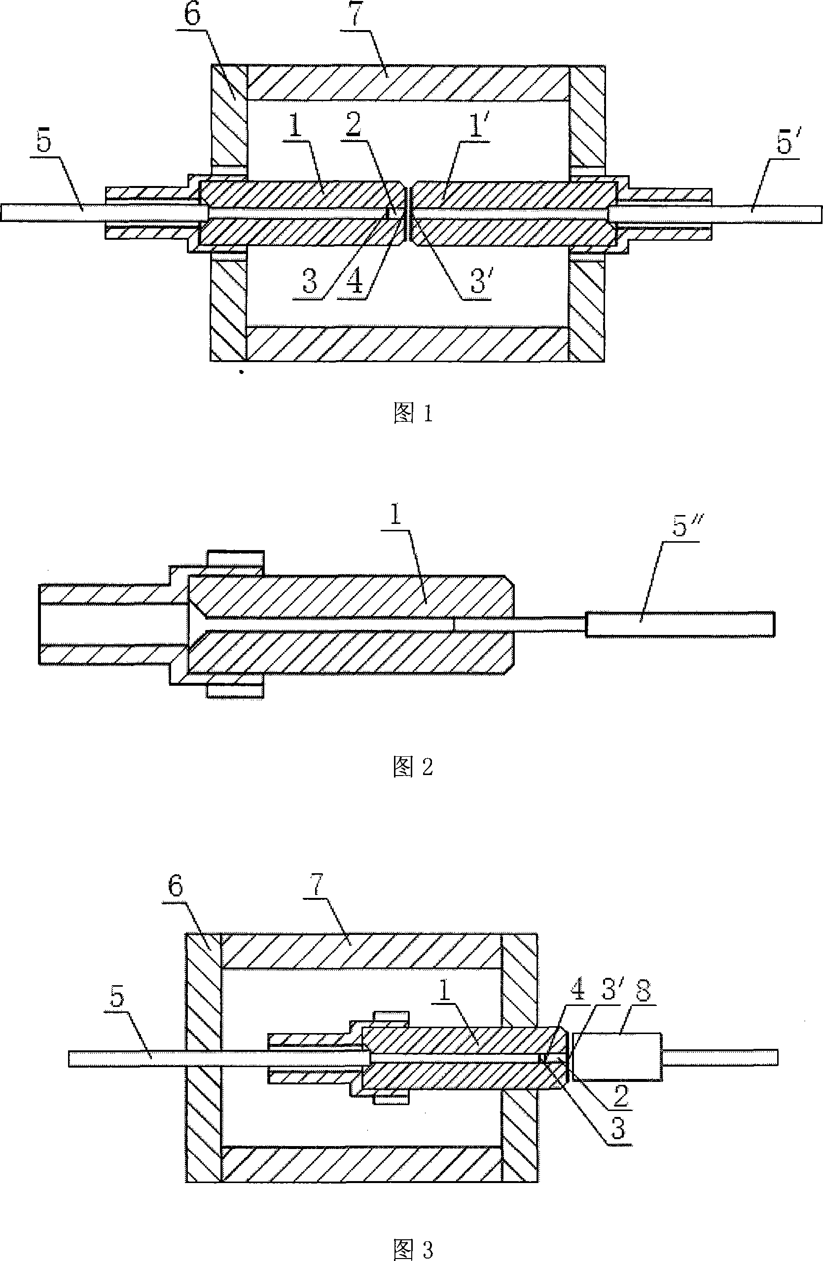
[0026] The first structure of the tunable optical fiber FAB filter of the present invention is shown in FIG. 1 . The tunable optical fiber FAP filter includes two ferrules 1 and 1', a support 6 for fixing the ferrule, and a piezoelectric ceramic 7 for tuning the length of the FAP cavity; the inner hole of the ferrule 1 is fixed with an optical fiber 5 and the optical fiber waveguide 2, between the optical fiber 5 and the optical fiber waveguide 2 is a high reflection film 3, the optical fiber waveguide 2 is located between the high reflection film 3 and the end face of the ferrule 1, and the end face of the ferrule 1 is coated with an anti-reflection film 4; The optical fiber 5' is fixed by glue in the inner hole of the core 1', and the end face of the ferrule 1' is coated with a high reflection film 3'. The ferrules 1 and 1' are fixed on the support 6 after precise adjustment and alignment to form an optical fiber F-P filter, and the transmission wavelength can be tuned by ch...

Embodiment 2

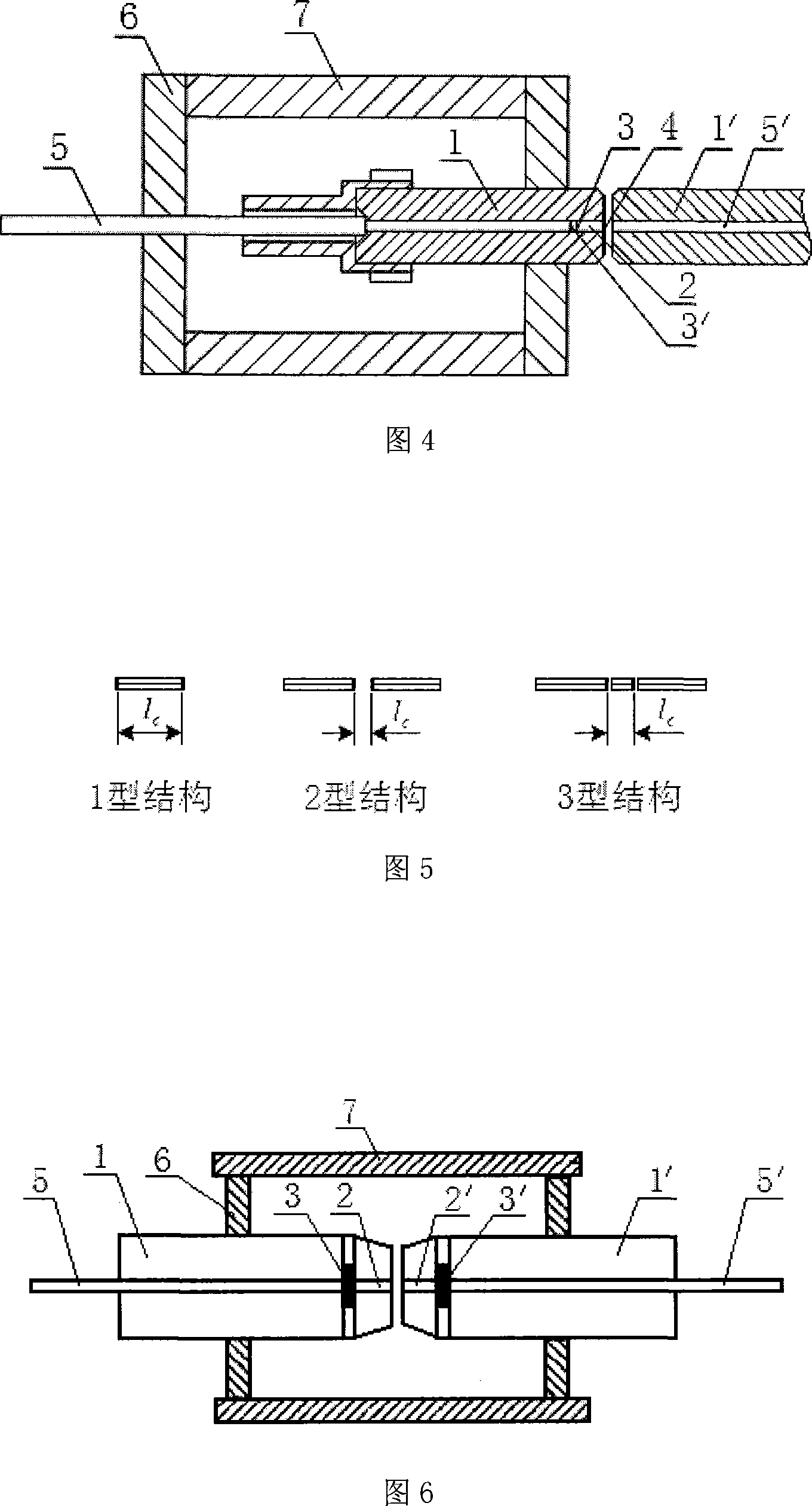
[0029] The second structure of the tunable optical fiber FAB filter of the present invention is shown in FIG. 3 . The tunable optical fiber FAP filter includes a ferrule 1, a support 6 for fixing the FAP filter, a piezoelectric ceramic 7 for tuning the FAP cavity length, and an optical fiber collimator 8 for receiving the transmitted light of the FAP filter; The fiber waveguide 2 is fixed by glue in the inner hole of the ferrule 1. One end face of the fiber waveguide 2 is located in the inner hole of the ferrule and is coated with an anti-reflection film 4 at the same time. The other end face is the end face formed by grinding the ferrule 1 and coated with High reflection film 3'; the optical fiber 5 is inserted into the inner hole of the ferrule 1 from the tail of the ferrule 1, and the end surface is coated with a high reflection film 3. The optical fiber 5 can move along the axis of the inner hole of the ferrule 1, and changing the position of the optical fiber 5 in the inn...


PUM

PropertyMeasurementUnit
lengthaaaaaaaaaa
lengthaaaaaaaaaa

Abstract

The present invention discloses a tunable optical fiber Fabry-Pero filter. The object is to provide the tunable optical fiber Fabry-Pero filter with a Fabry cavity optical fiber waveguide, easy manufacturing and low cost. The present invention comprises a core inset (1), the optical fiber waveguide (2), a high reflecting coating (3), an antireflection coating (4), an optical fiber (5), a support (6), a piezoelectric ceramics (7) and a fiber collimator (8); the optical fiber waveguide is fixed in one inner hole of the core insert. One end surface is placed in the inner hole of the core insert and the other end surface is placed on the same flat with the core insert end surface. The inner hole of the core insert which fixes the optical fiber waveguide is also inserted by the optical fiber. The optical fiber and the optical fiber waveguide are automatically aligned through the inner hole of the core insert. One of the two adjacent end surfaces of the optical fiber and the optical fiber waveguide is coated with the high reflecting coating. The end surface of the core insert or the other end surface of the core insert with optical fiber is coated with the high reflecting coating, so the optical fiber Fabry-Pero filter is formed.

Description

technical field [0001] The invention relates to an optical device used in an optical fiber communication system and an optical fiber sensing system, in particular to a tunable optical fiber Fabry-Perot filter. Background technique [0002] Tunable optical fiber Fabry-Perot (Fabry-Perot, FP, Fabry) filter is an important optical filter, which is a key component of modern optical fiber communication systems and optical fiber sensing systems, and has a wide range of uses, such as Optical performance monitoring in optical communication, optical noise filtering, noise suppression of optical amplifiers, channel selection and locking in wavelength division multiplexing systems, and wavelength tuning of laser light sources; in optical fiber sensing systems, tunable fiber optics Filters are used for wavelength scanning and are key devices in wavelength demodulation and spectral analysis systems. [0003] The optical fiber FAP filter is composed of a pair of optical fibers coated wit...

Claims


Application Information

Patent Timeline
Patent Type & Authority Applications(China)
IPC IPC(8): G02B6/34G02B6/26
Inventor 江毅唐才杰
Owner BEIJING INSTITUTE OF TECHNOLOGYGY
Why Eureka
Try Eureka