Composite multi-mode plasma surface processing device
A surface treatment device, plasma technology, applied in the direction of ion implantation plating, coating, metal material coating process, etc., can solve problems such as unfavorable workpieces and affect the performance of the film layer, so as to improve the bonding force of the film base and optimize the film. Layer structure and performance control, good effect of film layer performance
- Summary
- Abstract
- Description
- Claims
- Application Information
AI Technical Summary
Problems solved by technology
Method used
Image

Examples
specific Embodiment approach 1
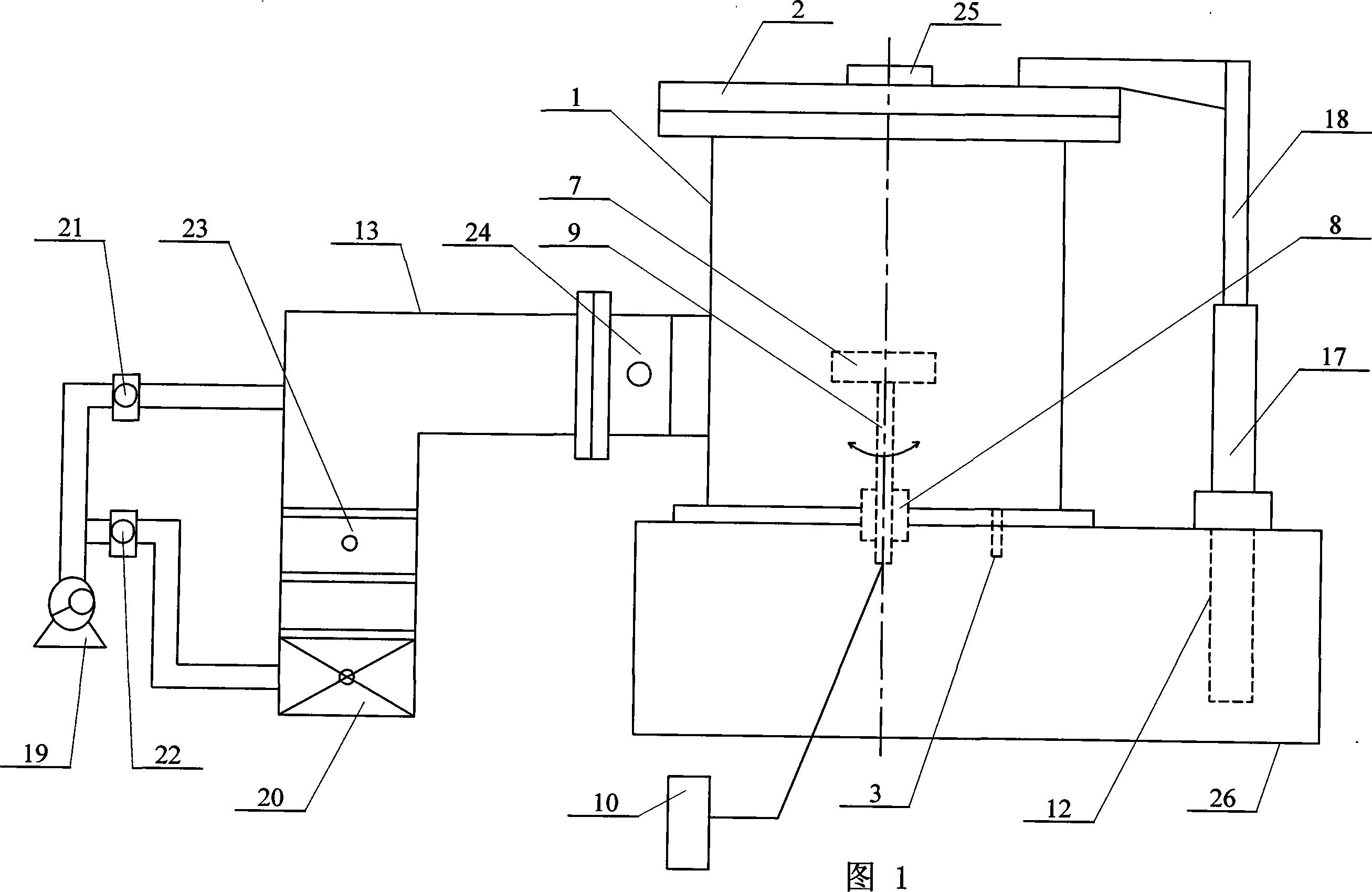
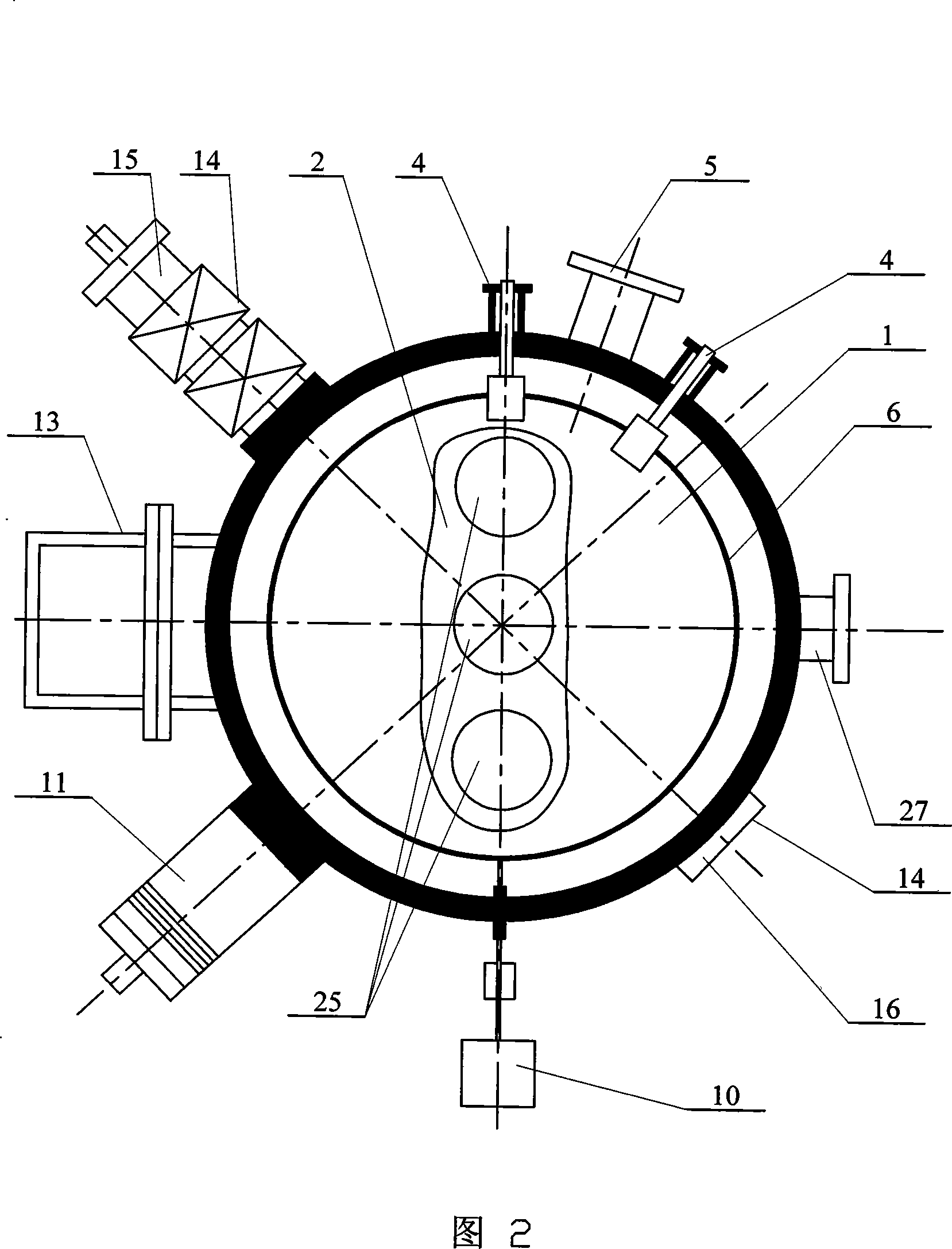
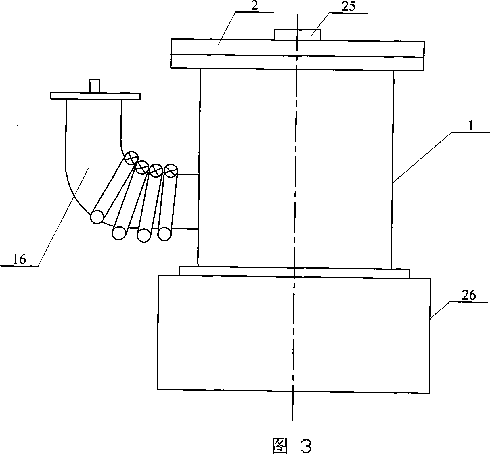
[0007] Specific Embodiment 1: This embodiment is described in conjunction with FIGS. 1 to 3. This embodiment consists of a vacuum chamber 1, a vacuum chamber upper cover 2, a magnetron sputtering target 4, a low-energy ion source 5, a radio frequency antenna 6, and a high-voltage target platform 7. , sealing insulating part 8, central electrode 9, pulse bias power supply 10, metal ion implantation source 11, chassis 26, pneumatic device 12, pump group 13, vacuum cathode arc source 14 is made up; Described vacuum cathode arc source 14 is made up of a The straight tube vacuum cathode arc source 15 and a 90° elbow vacuum cathode arc source 16 are composed of the two magnetron sputtering targets 4, a straight tube vacuum cathode arc source 15, and a 90° elbow vacuum cathode arc source 16 , a metal ion implantation source 11, a low-energy ion source 5 and a group of pump groups 13 are fixedly installed in the through hole on the outer wall of the vacuum chamber 1, and the radio freq...
specific Embodiment approach 2
[0008] Specific embodiment two: illustrate this embodiment in conjunction with Fig. 1, the pneumatic device 12 of this embodiment is made up of cylinder 17 and cylinder piston 18; One end is contained in the cylinder 17, and the cylinder 17 is fixed on the underframe 26. With such arrangement, the structure is simple and easy to operate, and the upper cover of the vacuum chamber can be opened and closed at any time. Other composition and connection relationship with
[0009] The specific embodiment one is the same.
specific Embodiment approach 3
[0010] Specific Embodiment 3: This embodiment is described with reference to FIG. 1 . The sealing and insulating member 8 of this embodiment is made of polytetrafluoroethylene insulating material or ceramic (glazed 95 porcelain) insulating material, which has better sealing performance. Other compositions and connections are the same as those in Embodiment 1 or 2.
[0011] Embodiment 4: This embodiment is described in conjunction with Fig. 1 and Fig. 2. The pump group 13 of this embodiment is composed of a mechanical pump 19, a molecular pump 20, a first valve 21, a second valve 22, a gate valve 23, and a grating valve 24. Composition; the output end of the mechanical pump 19 is respectively connected to the input end of the grating valve 24 and the molecular pump 20 through the first valve 21 and the second valve 22, and the output end of the molecular pump 20 is connected to the input end of the gate valve 23, The output end of the gate valve 23 is connected to the input end...
PUM
| Property | Measurement | Unit |
|---|---|---|
| Diameter | aaaaa | aaaaa |
| Thickness | aaaaa | aaaaa |
| Diameter | aaaaa | aaaaa |
Abstract
Description
Claims
Application Information
 - R&D
- Intellectual Property
- Life Sciences
- Materials
- Tech Scout
- Unparalleled Data Quality
- Higher Quality Content
- 60% Fewer Hallucinations
Browse by: Latest US Patents, China's latest patents, Technical Efficacy Thesaurus, Application Domain, Technology Topic, Popular Technical Reports.
© 2025 PatSnap. All rights reserved.Legal|Privacy policy|Modern Slavery Act Transparency Statement|Sitemap|About US| Contact US: help@patsnap.com