Optical fiber multi-point temperature and pressure measuring method for intelligent well and the device therefor

A technology of optical fiber temperature and multi-point temperature, which is applied in the field of smart wells, can solve problems such as large insertion loss, spectral interference, and temperature crosstalk, and achieve the effects of long service life, good stability, and use without ignition

Inactive Publication Date: 2008-05-28
北京蔚蓝仕科技有限公司 +1
View PDF0 Cites 28 Cited by
  • Summary
  • Abstract
  • Description
  • Claims
  • Application Information

AI Technical Summary

Problems solved by technology

[0007] The purpose of the present invention is to solve the problem of simultaneously monitoring the pressure and temperature of multiple oil layers with an optical fiber sensor in a high-temperature environment, and to provide an optical fiber multi-point temperature and pressure measurement method and device for smart wells. The present invention is effective It solves the problem that the insertion loss of fiber optic Fabry-Perot technology is too large, and multiple sensors are cascaded to form spectral interference with each other, making it suitable for realizing distributed pressure sensing, thus solving the problem of fiber grating technology used in Pressure drift and temperature crosstalk problems in pressure sensors

Method used


Image

  • Optical fiber multi-point temperature and pressure measuring method for intelligent well and the device therefor
  • Optical fiber multi-point temperature and pressure measuring method for intelligent well and the device therefor
  • Optical fiber multi-point temperature and pressure measuring method for intelligent well and the device therefor

Examples


Embodiment Construction

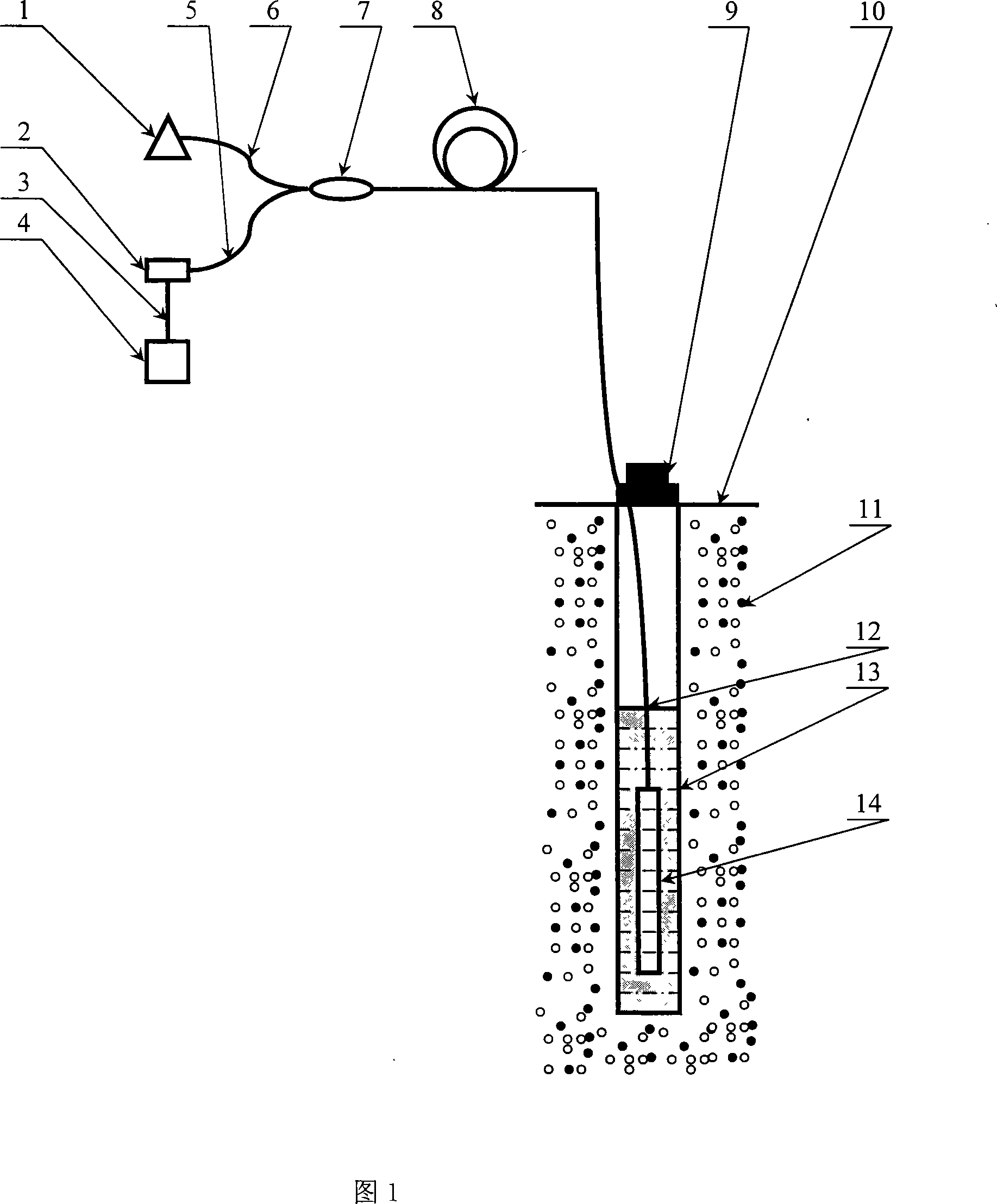
[0029] The optical fiber multi-point temperature and pressure measurement method and device for smart wells proposed by the present invention are described in detail in conjunction with the accompanying drawings and embodiments as follows:

[0030] Measuring method of the present invention is described as follows in conjunction with Fig. 1:

[0031] The light emitted from the broadband light source 1 is coupled and injected into the optical fiber 6, and injected into the optical cable 8 composed of optical fibers through the optical fiber coupler 7; the optical fiber temperature sensor and the optical fiber pressure sensor group 14 are distributed on the optical fiber cable 8, and the optical fiber temperature sensor and the optical fiber pressure sensor group 14 Under the action of external temperature and pressure, the reflected spectra are respectively modulated, and then pass through the optical cable 8 again in the reverse direction, and then inject into the modular spectr...


PUM


Abstract

The invention relates to a measuring method and a device for measuring optical fiber multipoint temperature and pressure of an intelligent well, belonging to the technical field of intelligent wells. The measuring method comprises that a plurality of optical fiber temperature sensors and optical fiber pressure sensors are arranged on an optical cable, wherein reversed lights which are reflected by the optical fiber temperature sensors and the optical fiber pressure sensors are respectively transformed into spectroscopic data which is transmitted to a processor, thereby respectively obtaining reflectance spectrums of all sensors, and a wave length value which is relative to the largest reflection rate is used as characteristic parameter of relative temperature sensors, the length of the cavity of each pressure sensor is calculated to be used as characteristic parameter of relative pressure sensors, and then the characteristic parameters of relative temperature and relative pressure sensors are compared with the characteristic parameter calibration curve to gain temperature reading or pressure reading of the optical fiber sensors. The device comprises a broad band light source, a modularized optical spectrometer, a data transmission line, a data processor, a first section optical fiber and a second section optical fiber, a optical fiber coupling, an optical cable, and a two-parameter sensor group of optical fiber temperature and optical fiber pressure. The invention solves the problems of pressure float and temperature crossfire when optical fiber grating technology is applied to a pressure sensor.

Description

technical field [0001] The invention belongs to the technical field of intelligent wells, and particularly relates to the design of an all-fiber sensor that can read the temperature and pressure of different positions or different oil layers in an oil well in real time through an optical cable and a demodulator on the ground. Background technique [0002] Smart well technology began in the 1990s. Under the general trend of the global oil industry to increase reservoir productivity at that time, smart well technology was developed and commercialized. The research and development of this technology has enabled the development of many marginal oil fields that could not be exploited before, and brought hope to the development of deep water, offshore, remote areas and old oil fields. The so-called smart well is a well in which sensors, data transmission systems and control equipment that can obtain downhole oil and gas production information are installed in the well, and data co...

Claims


Application Information

Patent Timeline
Patent Type & Authority Applications(China)
IPC IPC(8): E21B47/06E21B47/07E21B47/135
Inventor 黄正宇
Owner 北京蔚蓝仕科技有限公司
Why Eureka
Try Eureka