Low-speed highly precise control system for magnetic suspending flying wheel electromotor based on n Hall sensors

A Hall sensor and flywheel motor technology, applied in the direction of single motor speed/torque control, electrical components, electromechanical devices, etc., can solve the problems of low speed and low accuracy, and achieve the effect of improving speed measurement accuracy and control accuracy

Inactive Publication Date: 2008-05-28
BEIHANG UNIV
View PDF0 Cites 55 Cited by
  • Summary
  • Abstract
  • Description
  • Claims
  • Application Information

AI Technical Summary

Problems solved by technology

[0003] The technical problem solved by the present invention is: to overcome the deficiency of low-speed and low precision of the magnetic levitation reaction flywheel mo

Method used


Image

  • Low-speed highly precise control system for magnetic suspending flying wheel electromotor based on n Hall sensors
  • Low-speed highly precise control system for magnetic suspending flying wheel electromotor based on n Hall sensors
  • Low-speed highly precise control system for magnetic suspending flying wheel electromotor based on n Hall sensors

Examples


Embodiment Construction

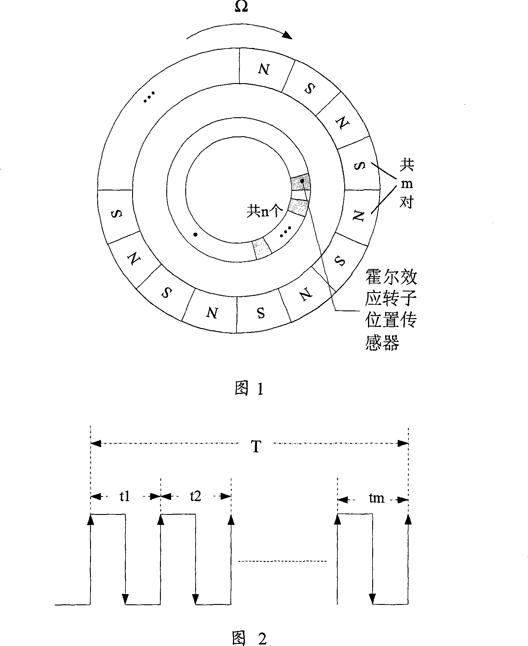
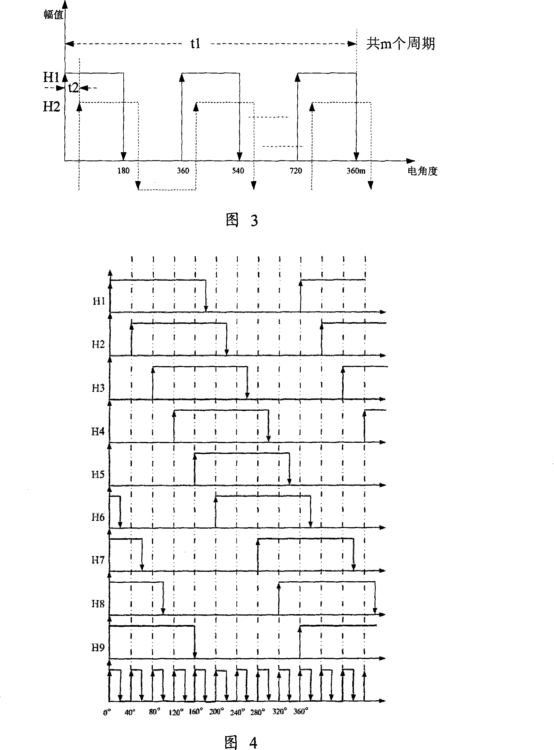
[0033] As shown in Figure 1, there are 9 Hall sensors used in the present invention, and the three-phase permanent magnet brushless DC motor adopts a hollow cup-shaped winding stator structure with 8 pairs of poles, no cogging and no iron core, and it is easy to install 9 Hall sensors. sensor. As shown in Figure 5, on the side corresponding to the pair of magnetic poles of the motor stator, n Hall sensors are evenly placed along the electrical angle of 40°, pasted on the motor stator, and aligned with the center line of the slot where the first end of the three-phase winding of the stator is located. , then the generated Hall signal 1 and Hall signal 2 have an electrical angle difference of 40°, as shown in Figure 3.

[0034] As shown in Figure 6, the control system of the present invention consists of FPGA module 7 as control, position detection 6, three-phase bridge power amplifier and drive circuit 4, three-phase permanent magnet brushless DC motor 5 with n Hall sensors , ...


PUM


Abstract

The invention provides a low-speed high-precision control system of a magnetically levitated flywheel motor based on n Hall transducers, which is used in the high-precision stance control executing mechanism of the new-generation high-stability satellite, namely, the drive control of the magnetically levitated reaction flywheel motor. The invention mainly comprises a controller taking the field programmable gate array (FPGA) as a core, a Hall transducer, a three-phase bridge power amplifier, a drive circuit of the power amplifier, a three-phase permanent magnet brushless DC motor, a voltage reducing chopper, an energy dissipation unit, a detecting unit of a winding current, a detecting unit of chopping voltage, and a DC constant power supply. By arranging n Hall transducers evenly on one side of the motor stator and detecting the Hall signals produced by the Hall transducers, precise rotation speed feedback can be obtained after the Hall signals are compensated, and the low-speed high-precision control of the magnetically levitated reaction flywheel used permanent magnet brushless DC motor can be implemented by using the controller taking the FPGA as the core.

Description

technical field [0001] The invention relates to a high-precision control system of a magnetic levitation flywheel permanent magnet brushless DC motor based on n Hall sensors, which is used to realize the high-precision and high-stability attitude control of a new generation of satellites, and is especially suitable for the attitude control of a magnetic levitation reaction flywheel . Background technique [0002] The high-precision and high-stability attitude control technology of the new generation of satellites is one of the key technologies that need a breakthrough. As the core actuator of the high-precision and high-stability attitude control system of the new generation satellite platform, the magnetic levitation reaction flywheel has the advantages of high angular momentum output precision, good control linearity, strong anti-interference ability and fast response speed, and has been recognized internationally. It has been gradually applied, and will become the preferr...

Claims


Application Information

Patent Timeline
IPC IPC(8): H02P6/06H02P6/16H02K29/08H02K11/00H02P6/17
Inventor 房建成朱娜刘刚王志强周新秀
Owner BEIHANG UNIV
Why Eureka
Try Eureka