Phase control focusing ultrasound wave source device

A technology for focusing ultrasound and wave sources, applied in the field of ultrasound wave sources, can solve the problems of increased equipment complexity, increased number of transducer array elements, and high cost, and achieve the effects of avoiding damage to normal tissues, excellent focusing performance, and enhanced focusing performance

Inactive Publication Date: 2008-06-04
INST OF ACOUSTICS CHINESE ACAD OF SCI
View PDF0 Cites 30 Cited by
  • Summary
  • Abstract
  • Description
  • Claims
  • Application Information

AI Technical Summary

Problems solved by technology

[0005] At present, ultrasonic phased array transducers are mainly divided into three types according to their array arrangement, namely linear array, planar array and circular array. The control circuit of the array transduc

Method used


Image

  • Phase control focusing ultrasound wave source device
  • Phase control focusing ultrasound wave source device
  • Phase control focusing ultrasound wave source device

Examples


Embodiment 1

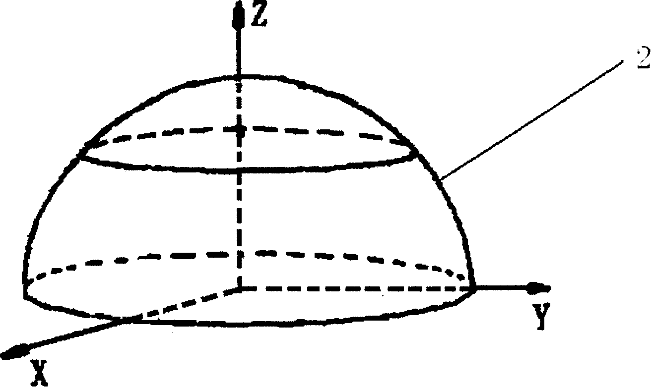
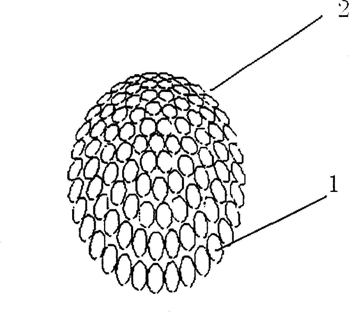
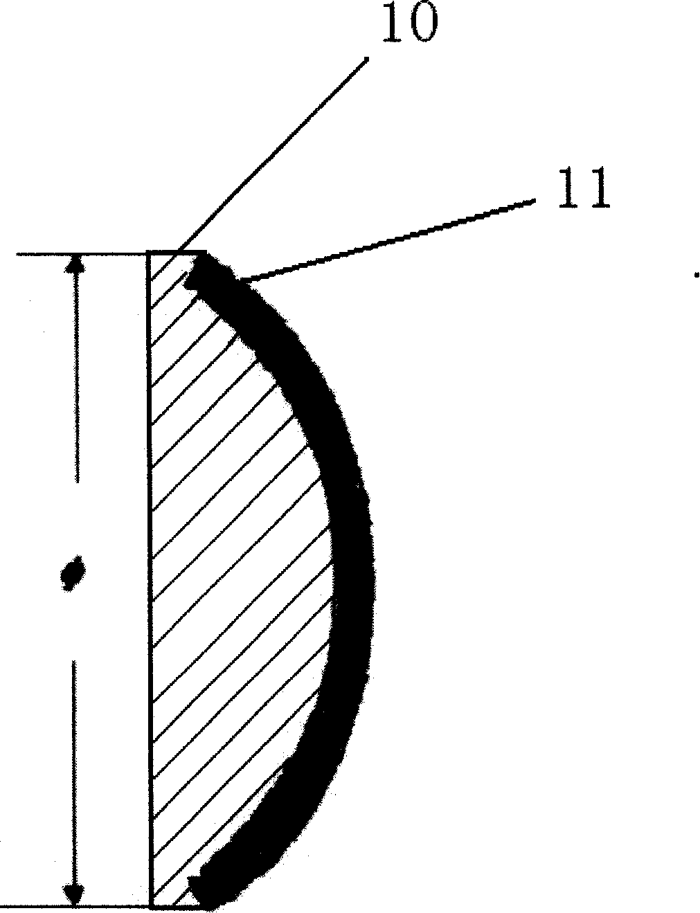
[0027] Referring to FIG. 1 , a source for phase-controlled focusing of ultrasonic waves includes a plurality of transducer array elements 1, such as 20, and a bearing part 2 that carries the transducer array elements 1, and the transducer array elements 1 It is cylindrical, the top is a piezoelectric wafer 11, and the bottom is a base 10. The base 10 and the piezoelectric wafer 11 are bonded as a whole by a glue-like adhesive. The bearing part 2 is concave spherical, and all the The transducer array element 1 is carried on the carrying member 2 so that all the piezoelectric wafers 11 are arranged in a concave spherical shape. The radius of the concave spherical surface is R=300mm, and the aperture angle is selected between 50° and 120°, such as 50°. The piezoelectric chip 11 is arc-shaped, so that the top of the transducer array element 1 is a circular convex surface.

[0028] The bearing part 2 can be made by conventional technology, such as using metal materials to make a s...

Embodiment 2

[0032] Referring to FIG. 1 , a source for phase-controlled focusing of ultrasonic waves includes a plurality of transducer array elements 1, such as 10, and a bearing member 2 carrying the transducer array elements 1, and the bearing member 2 is a concave spherical surface All the transducer array elements 1 are carried on the bearing part 2 so that all the piezoelectric wafers 11 are arranged in a concave spherical shape. The radius R of the concave spherical surface is 300 mm, and the aperture angle is selected between 50° and 120°, for example, 120°. The piezoelectric chip 11 is arc-shaped, so that the top of the transducer array element 1 is a circular concave surface.

[0033] refer to image 3 , the transducer array element 1 is cylindrical, and the diameter of the bottom surface is 5 mm to 20 mm, which is selected as 20 mm here. The base material is selected as a material with a lower density, such as a resin material, specifically 618 epoxy resin material, with a thi...

Embodiment 3

[0037] Referring to FIG. 1 , the carrying part 2 is in a concave spherical shape, and all the transducer array elements 1 are carried on the carrying part 2 so that all the piezoelectric wafers 11 are arranged in a concave spherical shape. The radius R of the concave spherical surface is 300 mm, and the aperture angle is selected between 50° and 120°, such as 100°.

[0038] refer to Figure 4 , the piezoelectric wafer 11 is a wafer with a circular plane, and an acoustic lens is bonded to the top of the piezoelectric wafer 11. The acoustic lens can be a concave lens or a convex lens. Taking the convex lens as an example here, the top of the transducer array element 1 is Round convex. The transducer array element 1 is cylindrical, and the diameter of the bottom surface is 5 mm to 20 mm, which is selected as 10 mm here. The base material is selected as a material with a low density, such as a resin material, such as 618 epoxy resin material, with a thickness of 2mm-10mm, such a...


PUM

PropertyMeasurementUnit
Radiusaaaaaaaaaa
Bottom diameteraaaaaaaaaa
Thicknessaaaaaaaaaa

Abstract

The invention discloses a phase-control focusing ultrasonic source device, comprising a plurality of transducer array elements used for emitting ultrasonic and a bearing part used for bearing the transducer array elements. The transducer array elements are in cylinder shape; a piezoelectricity wafer on the top of the array element can be in round convex shape or round concave shape, or the top of the cylindrical array element is provided with a round piezoelectricity flat piece as well as an acoustic lens; the bottom of the array element is provided with a base which is bonded into a whole with the piezoelectricity wafer; the bearing part is a sphere concave surface; all the transducer array elements are born to the bearing part to lead all the piezoelectricity wafers to be arranged in sphere concave surfaces; the plurality of transducer array elements are connected with a phase control device which adjusts the phases of all array element emitting signals by using electronic technology, thus adjusting focus position and focusing direction. The invention has the advantages of reinforcing the focusing performance of the sphere phase-control arrays, being used for high-strength focusing ultrasonic therapy equipment, only destroying tumor tissue without damaging normal tissue, thus improving therapeutic effect.

Description

technical field [0001] The present invention relates to an ultrasonic wave source for treatment equipment, in particular to a wave source device for high-intensity focused ultrasound (High Intensity Focused Ultrasound, HIFU for short) treatment equipment. Background technique [0002] High-intensity focused ultrasound (HIFU) for local tumor treatment is a new technology developed in recent years for local hyperthermia treatment of tumors. It has become a new hotspot in cancer treatment research. Within a short period of time, the temperature in the tumor body rises sharply to achieve the purpose of destroying the tumor tissue. However, while the high-intensity ultrasound is focused on the tumor tissue, causing the temperature of the tumor body to rise rapidly in a short period of time, the radiation intensity of the parts other than the tumor body must be kept as low as possible to avoid damaging normal tissues of the human body, or causing Tissue damage, which requires a h...

Claims


Application Information

Patent Timeline
IPC IPC(8): B06B1/06B06B3/04H01L41/08A61N7/02A61B18/04A61B18/00
Inventor 孙德兴王君琳李小雪肖灵
Owner INST OF ACOUSTICS CHINESE ACAD OF SCI
Why Eureka
Try Eureka