Plasma display device

A display device and plasma technology, applied in the field of structure, can solve the problems of reduced panel reflectivity, reduced panel light-dark ratio, etc.

Inactive Publication Date: 2008-06-11
LG ELECTRONICS(NANJING) PLASMA CO LTD
View PDF0 Cites 0 Cited by
  • Summary
  • Abstract
  • Description
  • Claims
  • Application Information

AI Technical Summary

Problems solved by technology

[0003] However, when the above-mentioned plasma display panel is irradiated by external light such as indoor lighting, the reflectance of the panel is reduced due to the plurality of electrodes formed in the panel, and the light-dark ratio of the bright room of the panel is reduced.

Method used


Image

  • Plasma display device
  • Plasma display device
  • Plasma display device

Examples


Embodiment Construction

[0015] The preferred embodiments are given below, and the plasma display device in the present invention will be described in detail in conjunction with the accompanying drawings.

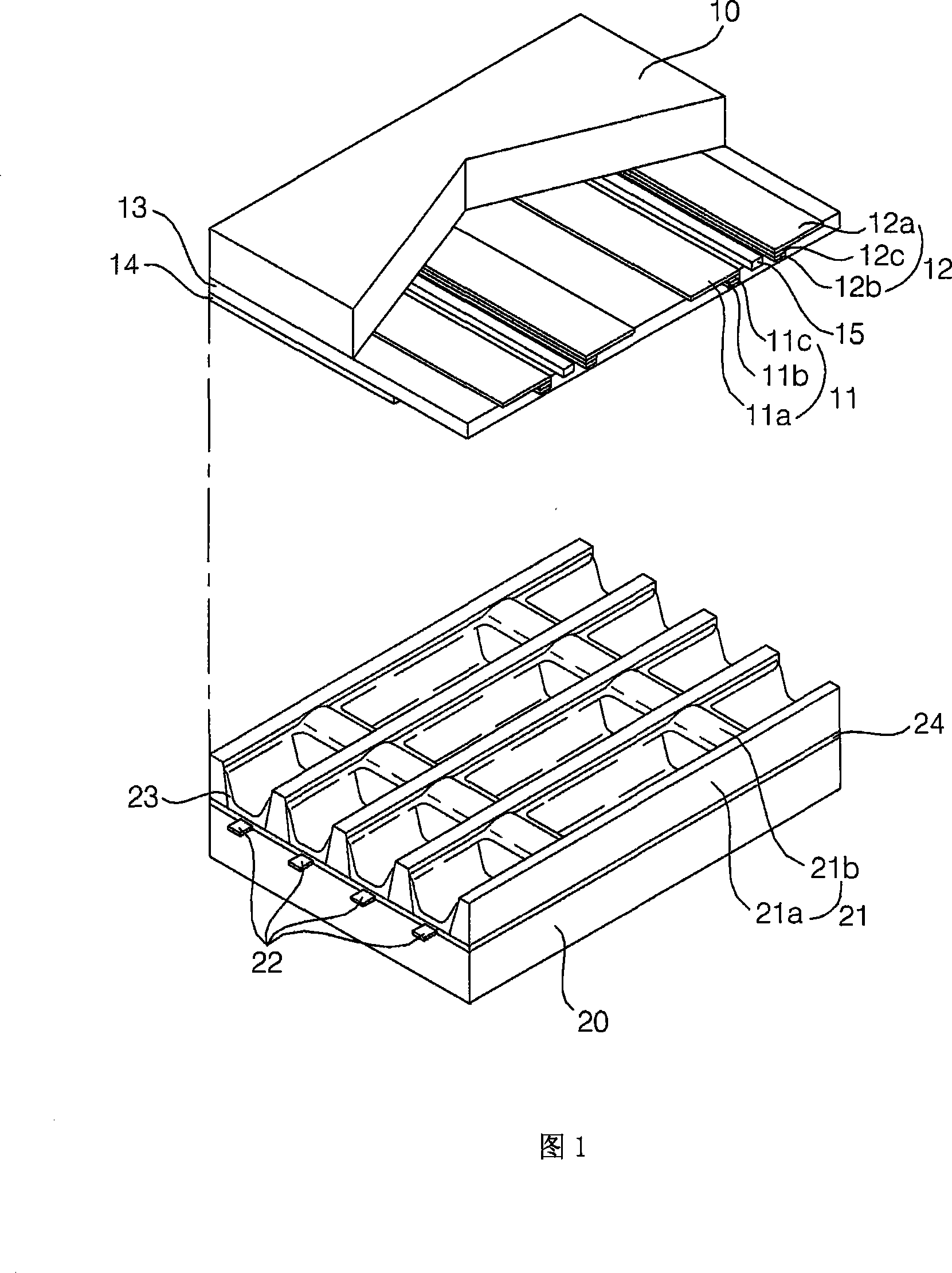
[0016] FIG. 1 is a schematic diagram of an embodiment of a structure of a plasma display panel.

[0017] As shown in FIG. 1 , the plasma display panel includes: a pair of sustain electrodes on an upper substrate 10 , that is, a scan electrode 11 and a sustain electrode 12 ; and a positioning electrode 22 formed on a lower substrate 20 .

[0018] The pair of sustain electrodes 11, 12 generally includes transparent electrodes (11a, 12a) and bus electrodes (11b, 12b) formed of indium tin oxide (Indium-Tin-Oxide; ITO), and the bus electrodes (11b, 12b) can be formed by Silver (Ag), chromium (Cr) and other metals or chromium / copper / chromium (Cr / Cu / Cr) are superimposed to form, or chromium / aluminum / chromium (Cr / Al / Cr) are superimposed to form. The bus electrodes (11b, 12b) are located on the transparent...


PUM


Abstract

A plasma display device is provided to enhance a dark / bright contrast of a PDP(Plasma Display Panel) by forming two electrodes on a upper substrate asymmetrically. First and second electrodes(540,550) are formed at asymmetrical positions from a center(560) of a discharge cell. A first distance between the center and the first electrode is different from a second distance between the center and the second electrode. A third distance between the first electrode and a corresponding barrier rib(500) is different from a fourth distance between the second electrode and a corresponding barrier rib(510). When the first electrode is closer to an external optical source than the second electrode, the second electrode is arranged to be closer to the center of the discharge cell than the first electrode.

Description

technical field [0001] The present invention relates to a plasma display (Plasma Display) device, and more particularly, to the structure of a plasma display panel (Panel) used in the above device. Background technique [0002] A general plasma display panel consists of an interlayer formed between the upper substrate and the lower substrate to form a unit cell (cell), and each cell (cell) is filled with neon (Ne), helium (He), or neon and helium The main discharge gas such as mixed gas (Ne+He) and a small amount of inert gas containing xenon. When the high-frequency voltage causes discharge, the inert gas generates vacuum ultraviolet rays (Vacuum Ultraviolet ray), which makes the phosphors formed between the interlayers emit light and display images. Such a plasma display panel has a light and thin structure, and is attracting attention as a next-generation display device. [0003] However, when the above-mentioned plasma display panel is irradiated with external light su...

Claims


Application Information

Patent Timeline
IPC IPC(8): G09F9/313H01J17/49H01J11/22H01J11/34
CPCH01J11/24H01J11/32H01J11/36H01J11/38H01J2211/323
Inventor 梁圣秀
Owner LG ELECTRONICS(NANJING) PLASMA CO LTD
Why Eureka
Try Eureka