Electrical ejection forming method and device for bonded permanent magnet

A technology of bonding permanent magnets and injection molding, which is used in the manufacture of circuits, electrical components, inductors/transformers/magnets, etc., which can solve the problems of poor stability and reliability of hydraulic control systems, long injection molding cycle of bonded permanent magnet products, and poor molding. The problems of low magnetic properties and dimensional accuracy of products can achieve the effects of shortened injection molding cycle, low hysteresis loss and high magnetic properties

Inactive Publication Date: 2008-06-11
WUYI UNIV
View PDF0 Cites 2 Cited by
  • Summary
  • Abstract
  • Description
  • Claims
  • Application Information

AI Technical Summary

Problems solved by technology

However, the traditional hydraulic injection molding method is currently used for the injection molding of bonded permanent magnets, and a complex hydraulic system is used for energy transmission and process control, so there are some obvious shortcomings: (1) The structure of the injection molding device Complex and large in size and weight; (2) The stability and reliability of the hydraulic control system are poor; (3) The energy consumption of the bonded permanent magnet product is large during the injection molding process; (4) The injection of the bonded permanent magnet product The forming cycle is long; (5) the working noise and environmental pollution are large; (6) the magnetic properties and dimensional accuracy of the formed products are low and the cost is high

Method used


Image

  • Electrical ejection forming method and device for bonded permanent magnet
  • Electrical ejection forming method and device for bonded permanent magnet
  • Electrical ejection forming method and device for bonded permanent magnet

Examples


Embodiment Construction

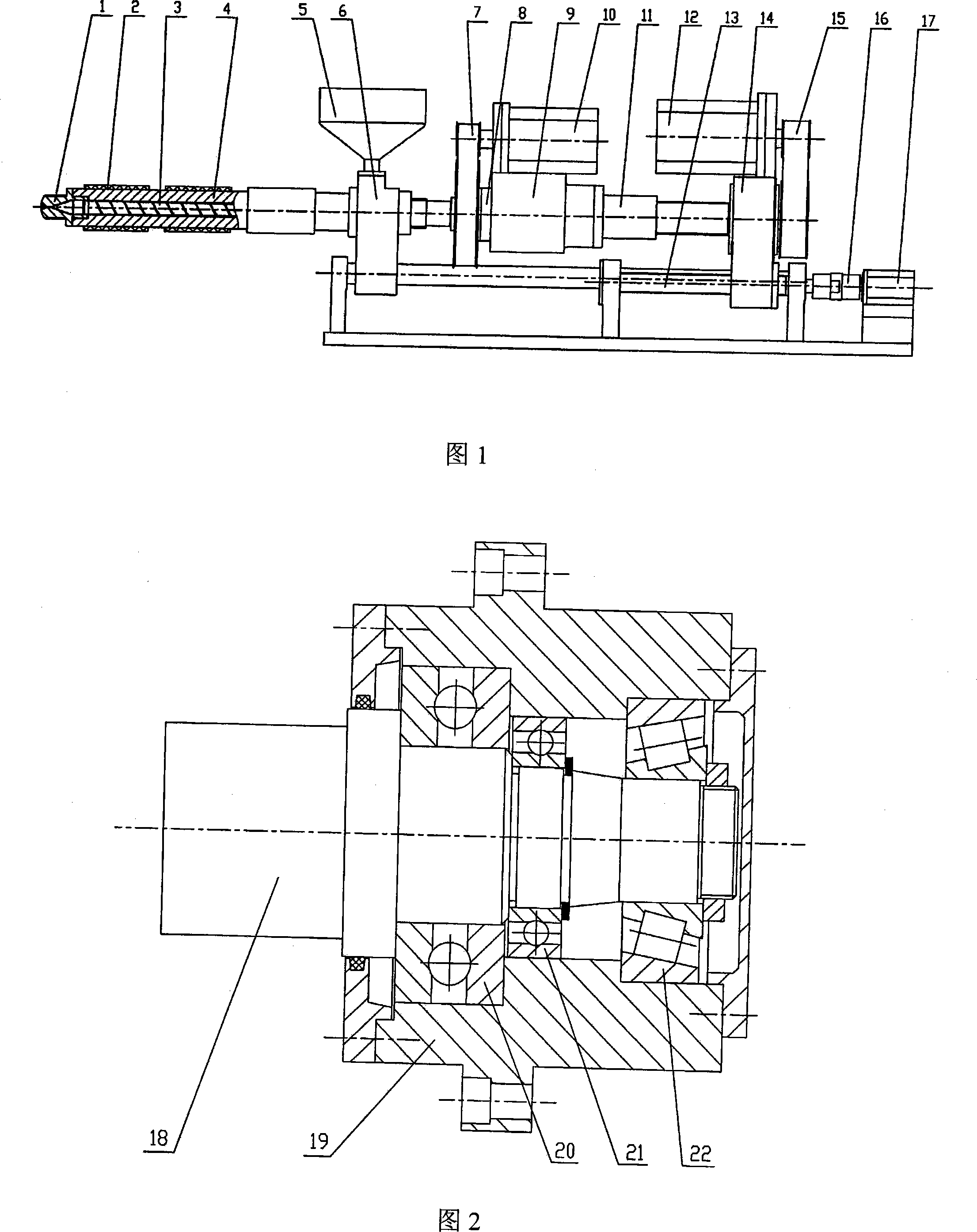
[0022] FIG. 1 is a schematic diagram of the structure of the apparatus used in the method of the present invention. The device mainly consists of a machine head (1), a heater (2), a screw (3), a barrel (4), a hopper (5), a front seat (6), a synchronous toothed belt (7, 15), a transmission shaft ( 8), the injection seat (9), the motor (10, 12, 17), the ball screw (11, 13), the rear seat (14), and the coupling (16). The bonded permanent magnet electric injection molding device is controlled by three motors: the motor connected to the screw through a synchronous toothed belt is called a plasticizing servo motor, and its function is to drive the screw to rotate, melt the magnet powder in the barrel and transport it forward; The motor connected to the injection seat through the synchronous toothed belt and the ball screw is called the injection servo motor. It drives the screw to inject forward or backward plasticize through the transmission shaft; the moving motor is driven by the...


PUM


Abstract

The invention relates to an electric operated injection molding method for bonded permanent-magnets and a device thereof. The method is that: an AC servomotor drives a timing belt and a ball screw to complete plasticization metering, stepless injection molding and guaranteeing the pressure to make up shrinks of a screw to mixed feeding of the bonded permanent-magnets. The device mainly comprises a screw rod, a charging barrel, the timing belt, a transmission shaft, a motor and the ball screw. When the pressure of fusion feeding of the bonded permanent-magnets in the charging barrel reaches the set value, load of the injection servomotor is increased and current of the injection servomotor is increased correspondingly, the injection servomotor rotates reversely to drive the screw rod to retreat in order to realize the plasticization metering of the permanent-magnets feeding; when the fusion feeding of the bonded permanent-magnets in the charging barrel reaches the value of the plasticization metering, the injection servomotor rotates positively to drive the timing belt and the ball screw, the transmission shaft is utilized to make the screw rod advance axially so as to realize the stepless injection molding and guaranteeing the pressure to make up shrinks of the permanent-magnets feeding. The whole device of the invention has good symmetrical structure and movement stationarity, low energy consumption, short injection molding period, and high magnetic performance and dimensional precision.

Description

technical field [0001] The invention relates to an injection molding technology for processing bonded permanent magnets, in particular to a method and a device for electric injection molding of bonded permanent magnets. Background technique [0002] The third-generation rare earth permanent magnet materials represented by NdFeB are increasingly in demand in the computer, automobile industry and information industry. The market has smaller and smaller size requirements for magnets, higher and higher precision requirements, and more and more complex shape requirements. The traditional powder metallurgy pressing and forming manufacturing technology can no longer meet the requirements. Applying powder injection molding technology to the magnetic material processing industry can not only directly mass-produce magnets with complex shapes, but also because the magnet powder is surrounded by molten organic binder during the injection molding process, it is easy to rotate under the a...

Claims


Application Information

Patent Timeline
Patent Type & Authority Applications(China)
IPC IPC(8): H01F41/02B28B1/24
Inventor 杜遥雪
Owner WUYI UNIV
Why Eureka
Try Eureka