Drive device for vehicle and method of assembling the same

A drive system and vehicle technology, applied in the direction of traction, transmission, power unit, etc. driven by an engine, can solve the problem that the axial size of the drive system cannot be sufficiently reduced, the configuration cannot be fully configured, and the accuracy and efficiency of the assembled drive system can be reduced. question

Inactive Publication Date: 2008-06-18
TOYOTA JIDOSHA KK
View PDF5 Cites 13 Cited by
  • Summary
  • Abstract
  • Description
  • Claims
  • Application Information

AI Technical Summary

Problems solved by technology

However, there is no technology capable of fully configuring the components of the drive system for this type of vehicle, including the first electric motor, the differential portion, the second electric motor, and t...

Method used


Image

  • Drive device for vehicle and method of assembling the same
  • Drive device for vehicle and method of assembling the same
  • Drive device for vehicle and method of assembling the same

Examples


Embodiment 1

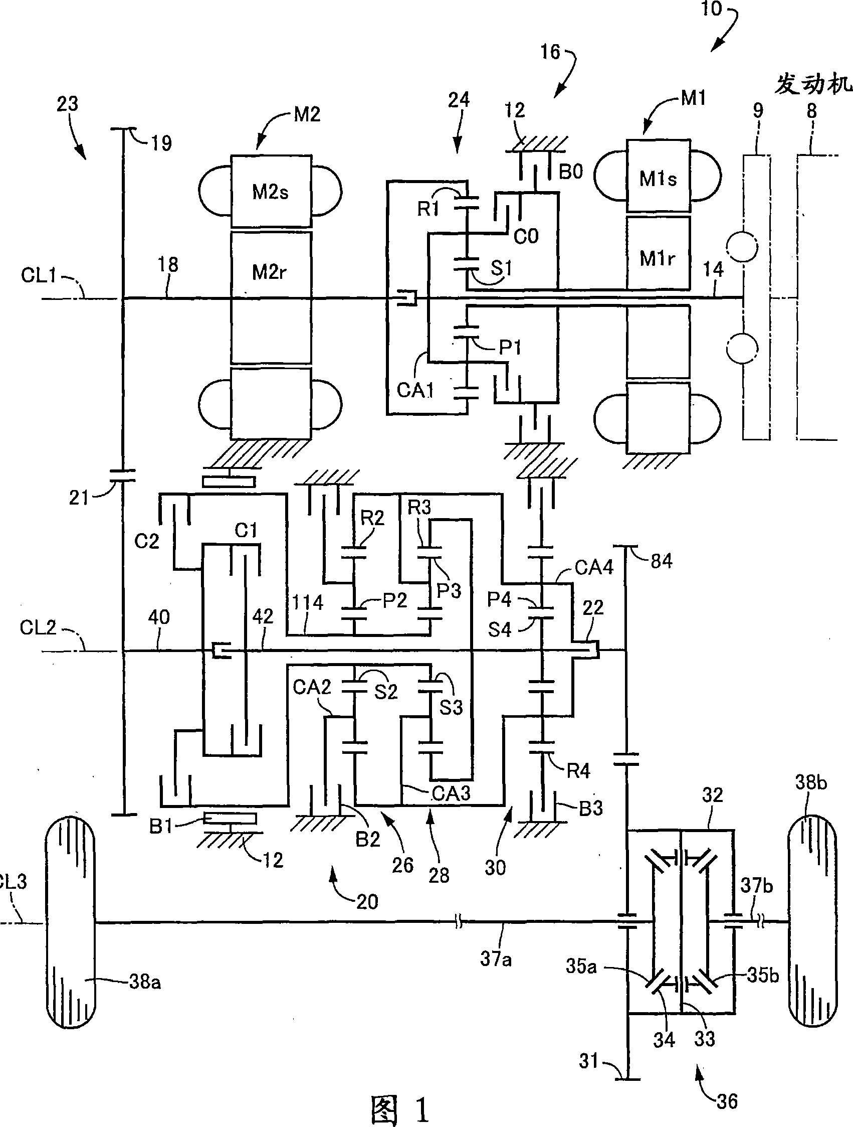
[0087] Reference is first made to the schematic diagram of FIG. 1 , which illustrates a drive system 10 for a hybrid vehicle constructed in accordance with one embodiment of the present invention. The drive system 10 shown in FIG. 1 includes: an engine 8; a transaxle housing 12 (hereinafter simply referred to as "housing 12"), which is a fixed member mounted on the vehicle body; a pulsation absorbing damper (vibration damping device) 9; an input shaft in the form of an input rotary member 14 connected to the engine 8 via the pulsation absorbing damper 9 and receiving the output of the engine 8 via the pulsation absorbing damper 9; a first electric motor M1; a hydraulically operated differential speed limiting device which is A form of a switching clutch C0 and a switching brake B0; a differential gear mechanism or a differential portion, which is in the form of a power distribution mechanism 16 connected to an input rotation member 14; a power transmission member 18, which is a...

Embodiment 2

[0166] Other embodiments of the present invention will be described below. In the following description of other embodiments, the same reference numerals as in the first embodiment are used to denote elements with the same function, and redundant descriptions thereof will be omitted.

[0167] Referring to FIG. 19 , which is a partial cross-sectional view showing a portion of a drive system 186 for a vehicle according to a second embodiment of the present invention. The drive system 186 differs from the drive system 10 of the first embodiment only in that a drive connection 188 is provided instead of the drive connection 23 . As shown in FIG. 19 , the driving connection device 188 includes a driving sprocket 190 , a driven sprocket 192 and a transmission belt 194 made of metal or resin and connecting the driving sprocket 190 and the driven sprocket 192 . The drive sprocket 190 is mounted on an axial end portion of the power transmission member 18 via the connection member 118 ...

Embodiment 3

[0169] Reference is next made to the partial cross-sectional view of FIG. 20 showing a portion of a drive system 196 for a vehicle according to a third embodiment of the present invention. The drive system 196 differs from the drive system 10 of the first embodiment in that the axial position of the engine 8 is opposite to that of the first embodiment, and between the differential drive gear 84 and the large diameter gear 31 of the final reduction gear unit 36 An idler gear 200 is arranged between them. The idler gear 200 is rotatably supported by the first and second housing parts 12a, 12b via bearings 198 . In the third embodiment, the fourth axis CL4 is disposed between and parallel to the second and third axes CL2, CL3, the idler gear 200 is rotatably supported around the fourth axis CL4, and is connected to the differential drive gear 84. It meshes with the large-diameter gear 31 of the final reduction gear unit 36 ​​. The idler gear 200 transmits the rotational motion ...


PUM


Abstract

A drive device for a vehicle having excellent assemblability. A first motor (M1), a power distribution mechanism (16), and a second motor (M2) are disposed on a first axis CL1, and an automatic transmission part (20) is disposed on a second axis CL2 parallel with the first axis CL1. A transmission member (18) positioned on the first axis CL1 at the opposite side end of an input rotating member (14) is connected to a first countershaft (40) positioned on the second axis CL2 at the opposite side end of the input rotating member (14) through a connection device (23) so that a power can be transmitted to each other. Since the axial dimensions of the first motor (M1), the power distribution mechanism (16), and the second motor (M2) installed on the first axis CL1 are approximately equal to theaxial dimension of the automatic transmission part (20) installed on the second axis CL2, these axial dimensions can be suitably reduced. Since a housing (12) is divided into four parts, i.e., a firstcase part (12a), a second case part (12b), a third case part (12c), and a fourth case part (12d), the housing can be easily assembled.

Description

technical field [0001] The present invention relates to a drive system for a vehicle including a first electric motor, a differential portion, a second electric motor and a transmission portion and a method of assembling the drive system for a vehicle, and more particularly, to a method for reducing the size of the drive system for a vehicle. Axial dimensions and technology to improve the assembly accuracy of drive systems for vehicles. Background technique [0002] There is known a drive system for a vehicle that includes a first electric motor, a differential portion, a second electric motor, and a transmission portion. Patent Document 1 discloses an example of such a drive system used in a hybrid vehicle. In the disclosed drive system for a hybrid vehicle, the first electric motor, the differential portion, the second electric motor, and the transmission portion are arranged coaxially with each other such that they are sequentially arranged in the axial direction of the ...

Claims


Application Information

Patent Timeline
IPC IPC(8): B60K6/46B60K6/365F16H3/72F16H61/32B60K6/26B60K6/36B60K6/40B60K6/405B60K6/445B60K6/543B60K6/547B60K17/04B60L50/16F02D29/02F02D29/06F16H57/02F16H57/021F16H57/023F16H57/031F16H57/04
CPCY02T10/6239Y02T10/6217Y02T10/7077Y02T10/62Y02T10/7072
Inventor 田端淳宫崎光史镰田淳史多贺丰
Owner TOYOTA JIDOSHA KK
Why Eureka
Try Eureka