Drive device for vehicle and method of assembling the same
A drive system and vehicle technology, applied in the direction of engine-driven traction, transmission, power plant, etc., can solve the problem of not being able to fully configure, reduce the accuracy and efficiency of the assembled drive system, and cannot fully reduce the axial size of the drive system, etc. question
- Summary
- Abstract
- Description
- Claims
- Application Information
AI Technical Summary
Problems solved by technology
Method used
Image
Examples
Embodiment 1
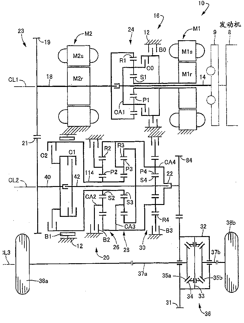
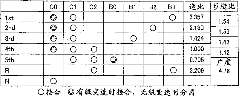
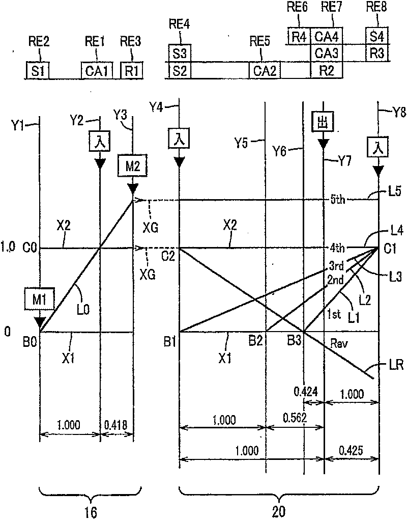
[0092] first reference figure 1 is a schematic diagram of a drive system 10 for a hybrid vehicle constructed in accordance with one embodiment of the present invention. figure 1 The illustrated drive system 10 includes: an engine 8; a transaxle housing 12 (hereinafter simply referred to as "housing 12"), which is a fixed member mounted to a vehicle body; a pulsation absorbing damper (vibration damping device) 9; a first input a shaft in the form of an input rotary member 14 connected to the engine 8 via the pulsation absorbing damper 9 and receiving the output of the engine 8 via the pulsation absorbing damper 9; a first electric motor M1; a hydraulically operated differential limiting device which is a switching clutch A form of C0 and switching brake B0; a differential gear mechanism or a differential portion, which is in the form of a power distribution mechanism 16 connected to an input rotation member 14; a power transmission member 18, which is arranged downstream of the...
Embodiment 2
[0171] Other embodiments of the present invention will be described below. In the following description of other embodiments, the same reference numerals as in the first embodiment are used to denote elements with the same function, and redundant descriptions thereof will be omitted.
[0172] refer to Figure 19 is a partial sectional view showing a part of a drive system 186 for a vehicle according to a second embodiment of the present invention. The drive system 186 differs from the drive system 10 of the first embodiment only in that a drive connection 188 is provided instead of the drive connection 23 . Such as Figure 19 As shown, drive connection 188 includes drive sprocket 190 , driven sprocket 192 , and drive belt 194 made of metal or resin and connecting drive sprocket 190 and driven sprocket 192 . The drive sprocket 190 is mounted on an axial end portion of the power transmission member 18 via the connection member 118 such that the drive sprocket 190 and the powe...
Embodiment 3
[0174] next reference Figure 20 is a partial sectional view showing a part of a drive system 196 for a vehicle according to a third embodiment of the present invention. The drive system 196 differs from the drive system 10 of the first embodiment in that the axial position of the engine 8 is opposite to that of the first embodiment, and between the differential drive gear 84 and the large diameter gear 31 of the final reduction gear unit 36 An idler gear 200 is arranged between them. The idler gear 200 is rotatably supported by the first and second housing parts 12a, 12b via bearings 198 . In the third embodiment, the fourth axis CL4 is disposed between and parallel to the second and third axes CL2, CL3, the idler gear 200 is rotatably supported around the fourth axis CL4, and is connected to the differential drive gear 84. It meshes with the large-diameter gear 31 of the final reduction gear unit 36 . The idler gear 200 transmits the rotational motion from the different...
PUM
 Abstract
Description
Claims
Application Information
 - R&D
- Intellectual Property
- Life Sciences
- Materials
- Tech Scout
- Unparalleled Data Quality
- Higher Quality Content
- 60% Fewer Hallucinations
Browse by: Latest US Patents, China's latest patents, Technical Efficacy Thesaurus, Application Domain, Technology Topic, Popular Technical Reports.
© 2025 PatSnap. All rights reserved.Legal|Privacy policy|Modern Slavery Act Transparency Statement|Sitemap|About US| Contact US: help@patsnap.com


