Steam generation plant and method for operation and retrofitting of a steam generation plant

A technology for generating equipment and steam generators, which is applied in steam engine installations, mechanical equipment, lighting and heating equipment, etc., and can solve the problem of realizing investment costs only after 20 years.

Inactive Publication Date: 2008-06-18
MAN TURBO AG
View PDF0 Cites 25 Cited by
  • Summary
  • Abstract
  • Description
  • Claims
  • Application Information

AI Technical Summary

Problems solved by technology

According to today's estimates, the remanufacturing of steam generating plants using the oxy-fuel method will only be possible some 10 to 20 years from now and will then entail enormous investment costs

Method used


Image

  • Steam generation plant and method for operation and retrofitting of a steam generation plant
  • Steam generation plant and method for operation and retrofitting of a steam generation plant
  • Steam generation plant and method for operation and retrofitting of a steam generation plant

Examples


Embodiment Construction

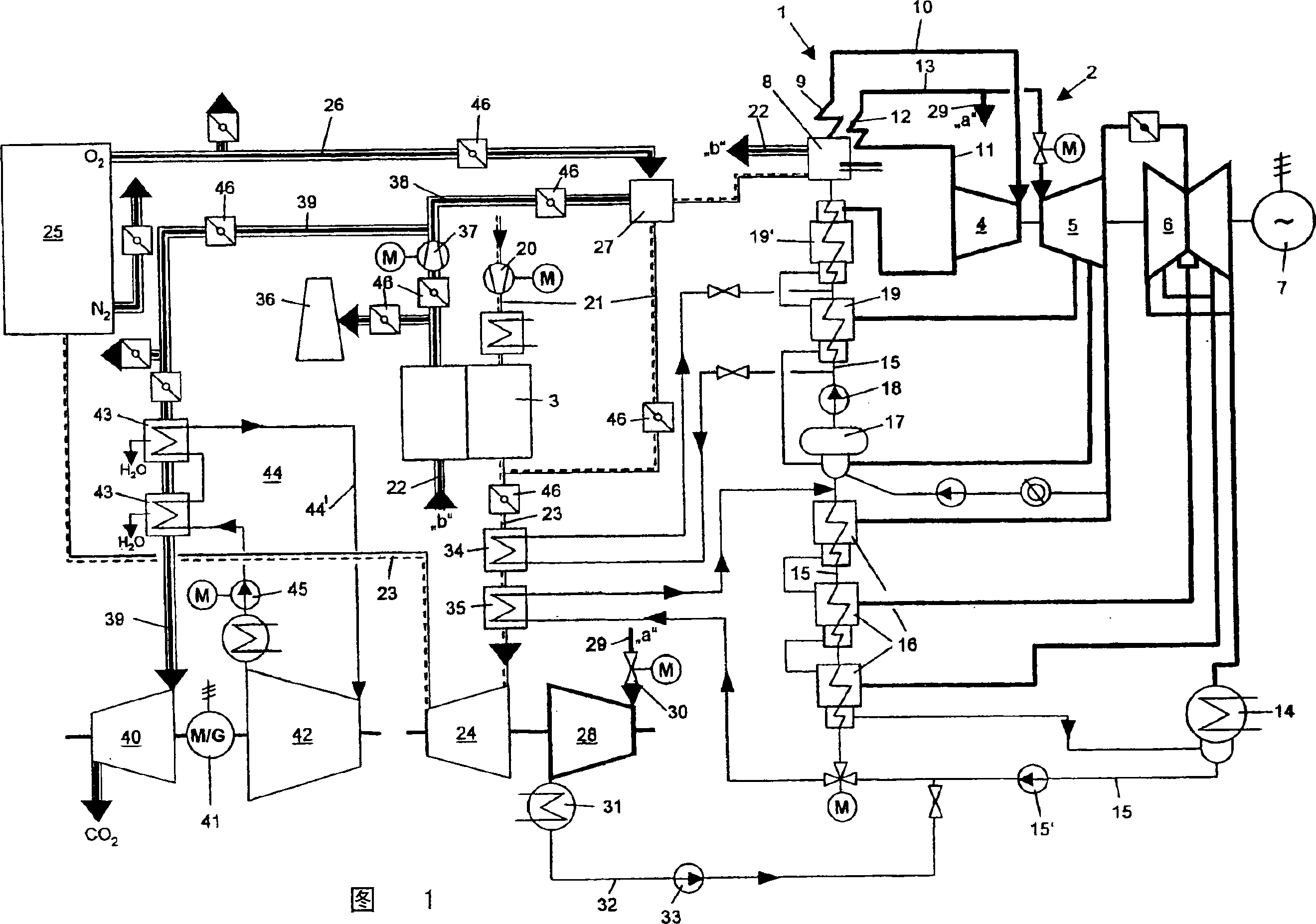
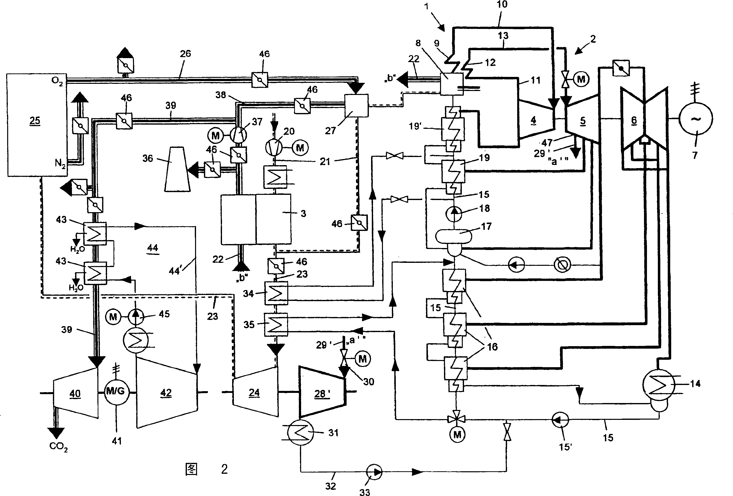
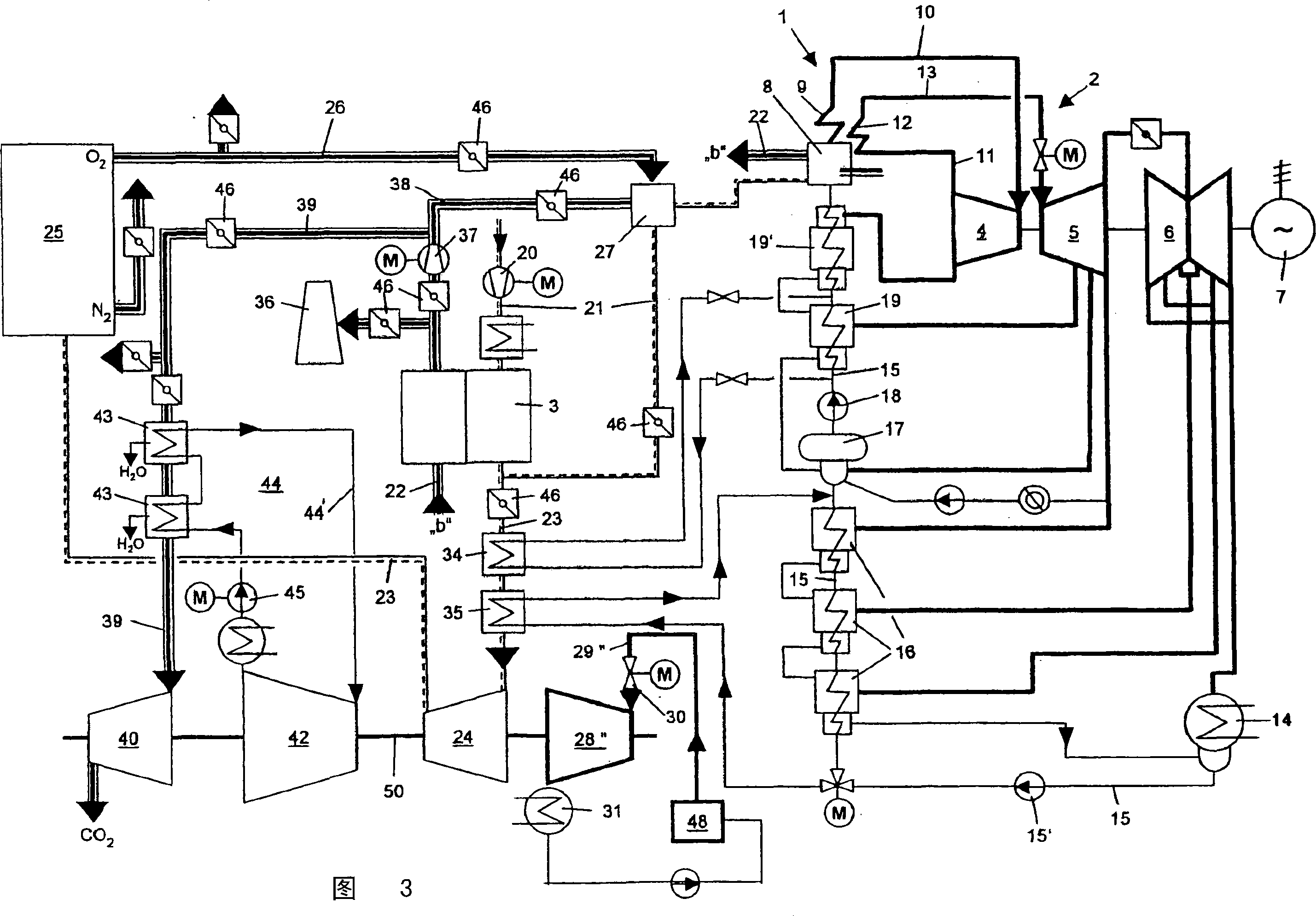
[0011] The steam generating plant comprises a steam generator 1 with a water-steam circuit, a steam turbine unit 2 as well as an air supply system, a flue gas discharge system and a regenerative air preheater heated by the flue gas (hot blast preheater 3 ). In this regard, the steam generating plant is of conventional construction type. What follows is only a brief explanation of the invention in terms of aspects necessary for understanding it.

[0012] The steam turbine unit 2 comprises a high-pressure part 4 , a medium-pressure part 5 and a low-pressure part 6 , which are arranged on a common shaft and drive a generator 7 for generating electrical energy.

[0013] The steam generator 1 shown is a forced continuous steam generator. The following descriptions also apply to drum boilers. The steam generator 1 has a combustion chamber 8 with a furnace chamber operated with gaseous fuel. In principle, operation on coal is also possible, taking into account the use of a flue ga...


PUM


Abstract

The invention relates to a steam generation plant, comprising a steam generator (1) with a combustion chamber (8), an evaporator, a superheater (9), an intermediate superheater (12), a condenser (14), a feed water preheater (16, 19, 19') regeneratively heated by steam, a steam turbine set (2) with a high-pressure section (4), a medium pressure section (5) and a low-pressure section (6), a flue gas line (22), connected to the combustion chamber (8), an air supply line (21), for the supply of combustion air to the burner in the combustion chamber (8) and an air preheater (3) with flue gas and combustion air passing therethrough. An air line (23) branches off from the air supply line (21) downstream of the air preheater (3) in said steam generation plant and supplies an air-fractionation unit (25). Air coolers (34, 35) are arranged in the air line (23) through which the condensate or feed water from the condensate / feed water circuit from the steam generator (1) flows. The oxygen output from the air fractionation unit (25) is connected to the burner of the combustion chamber (8) by means of an oxygen line (26).

Description

technical field [0001] The invention relates to a steam generating plant having the features stated in the preamble of claim 1 and to a method for operating or retrofitting a steam generating plant according to claim 17 or 23 . Background technique [0002] The steam generating equipment produces carbon dioxide through the combustion of fossil fuels, and the carbon dioxide destroys the ozone layer in the atmosphere. It is therefore jointly developed by industry and research institutes in the field of power plants to separate CO2 from flue gases. [0003] Within the scope of joint development is the conversion of carbon monoxide into carbon dioxide and hydrogen with water and the subsequent separation of carbon dioxide (IGCC (Integrated Gasification Combined Cycle) - process) and the combustion of fossil fuels with pure oxygen and subsequent separation of carbon dioxide (oxygen fuel (Oxy -Fuel) method). According to today's estimates, the remanufacturing of steam generating...

Claims


Application Information

Patent Timeline
Patent Type & Authority Applications(China)
IPC IPC(8): F01K3/20
CPCF25J3/04139F25J3/04969Y02E20/18F25J2230/80F01K3/20F25J2240/70F25J3/04618F25J3/04533F25J3/04115F25J3/04133F25J3/04109F25J3/046F25J2260/80F25J3/04018F25J3/04121Y02E20/34
Inventor B·格利克
Owner MAN TURBO AG
Why Eureka
Try Eureka