Eureka AIR delivers breakthrough ideas for toughest innovation challenges, trusted by R&D personnel around the world.

Exhaust gas treatment device regeneration inhibiting fuel combustion in engine cylinder

A technology for an exhaust gas treatment device and an engine system, which is applied to the electronic control of the exhaust gas treatment device, exhaust device, exhaust gas treatment, etc., can solve the problems of not providing beneficial results, increasing fuel consumption, and insufficient beneficial results.

Active Publication Date: 2008-06-25
VOLVO CAR CORP
View PDF2 Cites 4 Cited by
  • Summary
  • Abstract
  • Description
  • Claims
  • Application Information

AI Technical Summary

Problems solved by technology

However, the proposed solution increases fuel consumption
At the same time, since the energy used to heat the catalytic converter is transferred as heat, there is a large energy loss between the engine and the catalytic converter in the form of a drop in temperature
Where the catalytic converter is provided at a relatively remote distance from the engine, energy losses may render the measure either unable to provide beneficial results or to provide insufficient beneficial results
At the same time, when the engine system is equipped with an exhaust turbocharger, the energy loss will be further increased when the delayed ignition regeneration measures are taken

Method used

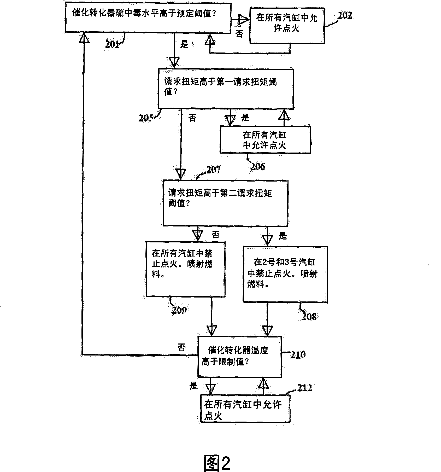
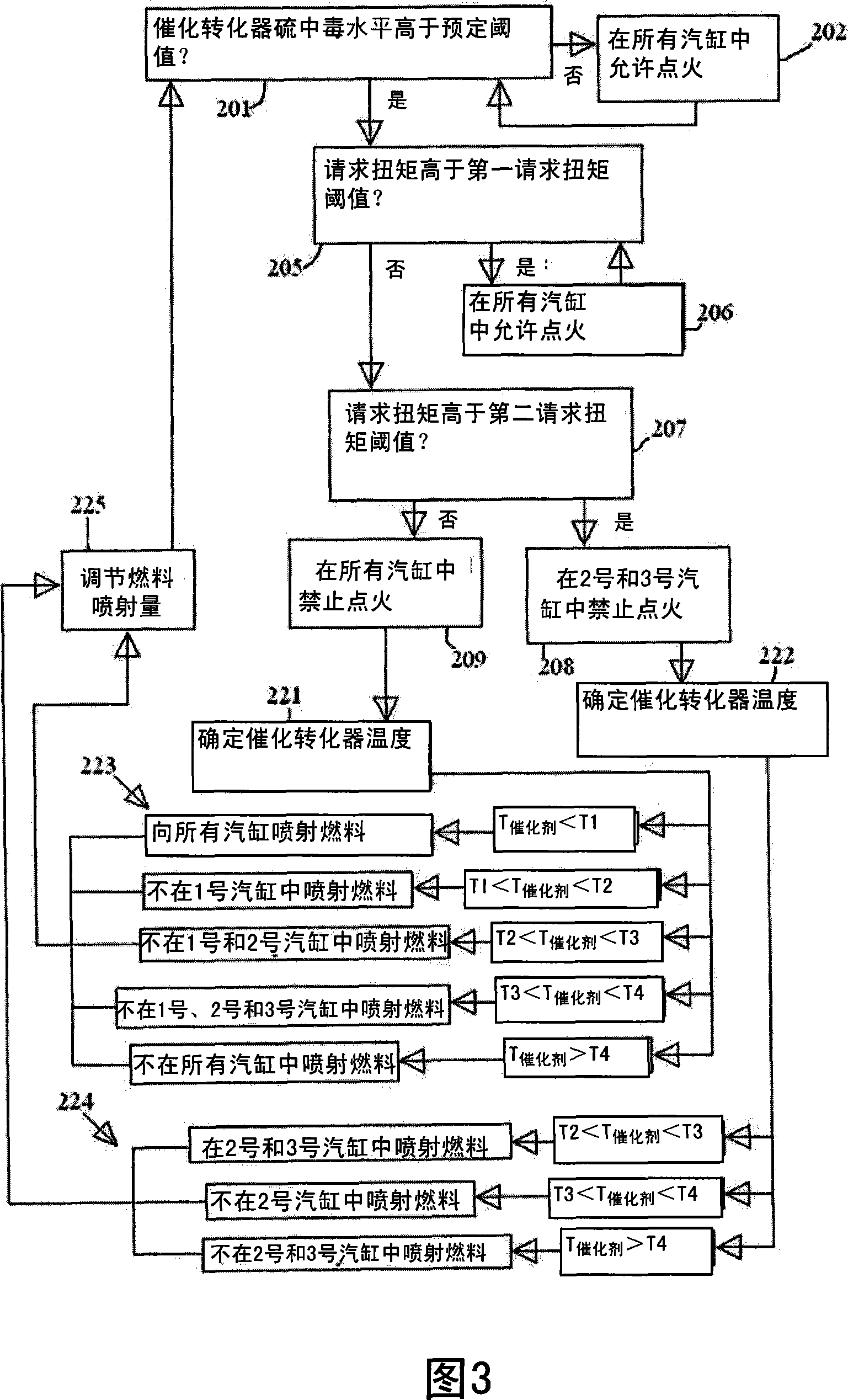

Image

  • Exhaust gas treatment device regeneration inhibiting fuel combustion in engine cylinder
  • Exhaust gas treatment device regeneration inhibiting fuel combustion in engine cylinder
  • Exhaust gas treatment device regeneration inhibiting fuel combustion in engine cylinder

Examples


Embodiment Construction

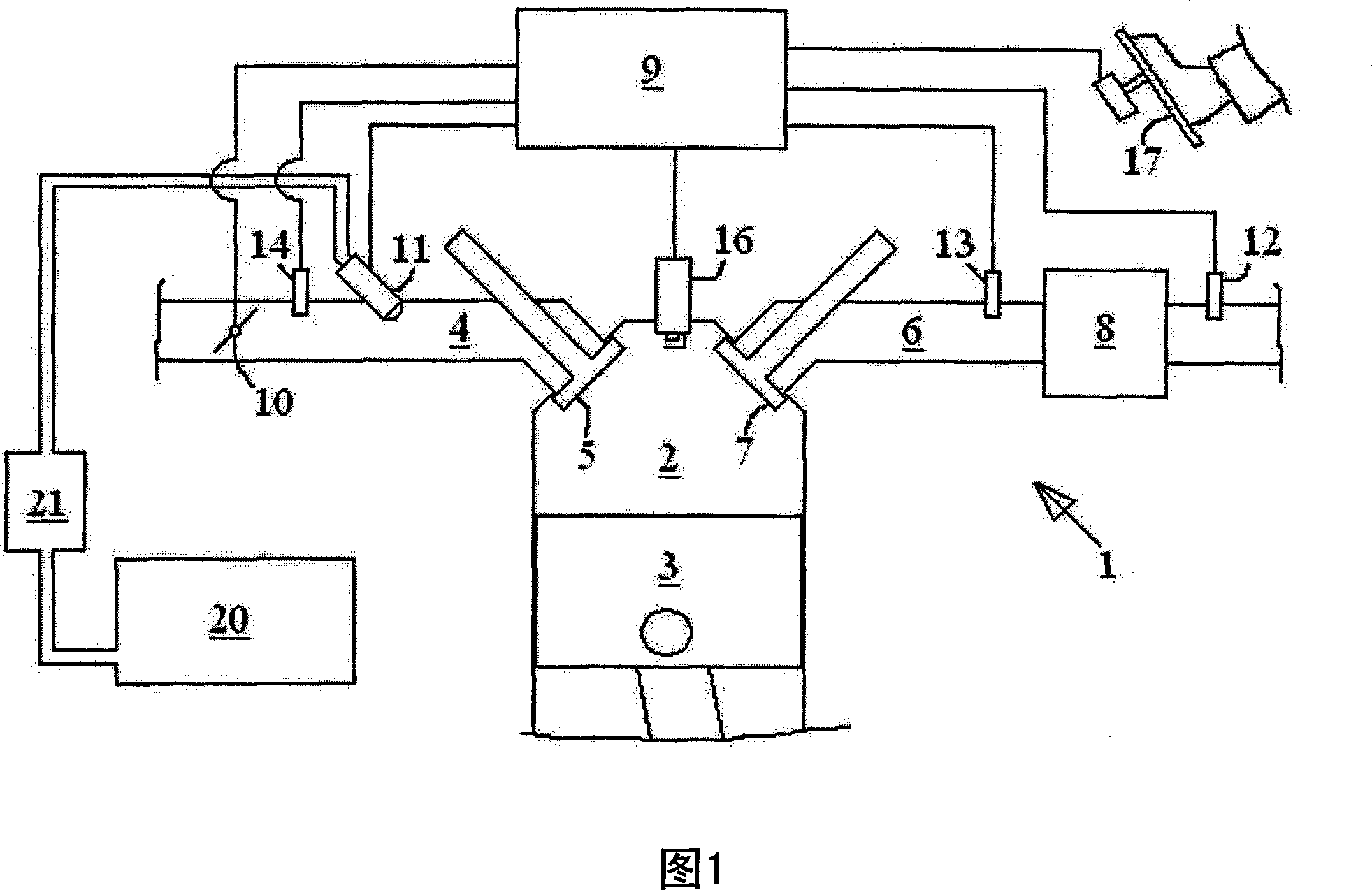
[0029] FIG. 1 shows a schematic diagram of various parts of an automotive engine system 1 including an internal combustion engine. The engine comprises four cylinders 2 each having a reciprocating piston 3, only one of which is shown in FIG. 1 . It should be noted that the invention is applicable to engines having any number of cylinders. The communication between each cylinder 2 and the intake port 4 is controlled by at least one corresponding intake valve 5 , while the communication between each cylinder 2 and the exhaust port 6 is controlled by at least one corresponding exhaust valve 7 . Downstream of the cylinder 2 an exhaust gas treatment device 8 in the form of a catalytic converter is provided.

[0030] The engine system 1 also includes an engine control unit (ECU) 9 which may be provided as one unit, or as more than one logically interconnected physical unit. The ECU 9 is adapted to control an air flow control device including a throttle valve 10 , and a fuel inject...


PUM


Abstract

A method for an exhaust gas treatment device (8) in an engine system, and an engine system comprising an internal combustion engine with at least one cylinder (2) are presented. The engine system further comprises fuel injection means (11) and an exhaust gas treatment device (8). The method comprises performing a combustion inhibition exhaust gas treatment device regeneration (208, 209, 223, 224,225), comprising inhibiting combustion in at least one of the cylinders (2), and controlling the fuel injection means (11) so that fuel is allowed into at least one of the cylinders (2) in which combustion is inhibited.

Description

technical field [0001] The invention relates to a method for an exhaust gas treatment device in an engine system comprising an internal combustion engine having at least one cylinder and a fuel injection device. The invention also relates to an engine system comprising an internal combustion engine having at least one cylinder and a fuel injection device, the engine system further comprising an engine control unit adapted to control the fuel injection device. Background technique [0002] Modern cars are equipped with exhaust treatment devices called catalytic converters, which convert gases such as hydrocarbons (HC), carbon monoxide (CO) and nitrogen oxides (NO x ) into toxic gases such as carbon dioxide (CO 2 ), nitrogen (N 2 ) and water (H 2 O) such substances. A known problem with catalytic converters is that certain species can remain on the inner surfaces of the catalytic converter, for example by physisorption or chemisorption, and degrade the performance of the c...

Claims


Application Information

Patent Timeline
Patent Type & Authority Applications(China)
IPC IPC(8): F01N3/025F01N9/00F02D41/02F02D43/00
CPCF02D41/266Y02T10/42F02D41/027F02D41/1446F02D37/02F01N3/206Y02T10/26F02D41/008F02D41/0002F02P9/002F02D41/025Y02T10/12Y02T10/40Y02A50/20
Inventor 约纳斯·赫尔曼松尼克拉斯·沃尔默安德斯·赫尔格·约翰森
Owner VOLVO CAR CORP
Why Eureka
Eureka Blog
Learn More