
Engineering machinery airborne teledata acquisition device and method

A construction machinery and remote data technology, applied in the direction of comprehensive factory control, comprehensive factory control, electrical program control, etc., can solve the problem of inability to realize multi-channel fast real-time data collection and analysis, no battery and charging circuit, waste of vehicle battery energy, etc. problem, to achieve the effect of no omission of time tags, high compatibility and scalability, and simple structure

Inactive Publication Date: 2008-06-25
SHANGHAI JIAO TONG UNIV
View PDF1 Cites 49 Cited by
  • Summary
  • Abstract
  • Description
  • Claims
  • Application Information

AI Technical Summary

Problems solved by technology

This technology has the following deficiencies: [1] There is only one CAN bus interface, which cannot meet the needs of many construction machinery dual-channel CAN bus data acquisition; [2] There is a real-time clock chip, but there is no battery and charging circuit. Record time, after re-power on, it will provide wrong time label; [3] Using single-chip microcomputer as the central processing unit, the on-chip resources are not enough, such as the serial port can not meet the needs, need to add a serial port switching circuit, the memory can not meet the needs, need to expand There is no off-chip memory, no on-chip CAN bus controller, external expansion is required, and the running speed is slow, so it cannot realize multi-channel fast real-time data acquisition and analysis; [4] use the control command of the host computer to control its power-off, instead of Delayed self-power-off, if the upper computer is not running, it will be out of control, wasting the energy of the vehicle battery; [5] There is no remote parameter setting function, and the scalability and versatility are poor

Method used


Image

  • Engineering machinery airborne teledata acquisition device and method
  • Engineering machinery airborne teledata acquisition device and method
  • Engineering machinery airborne teledata acquisition device and method

Examples


Embodiment Construction

[0050] Below in conjunction with accompanying drawing and the specific embodiment that is applied to the remote monitoring data acquisition of a QUY250A hydraulic crawler crane produced by Fudu Company, the present invention is described in detail: the present embodiment is carried out under the premise of the technical solution of the present invention, and given The detailed implementation and process are shown, but the protection scope of the present invention is not limited to the following examples.

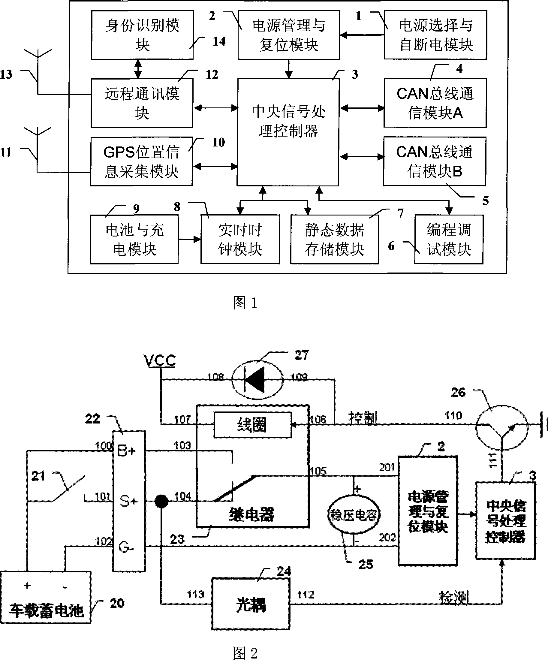
[0051] As shown in Fig. 1, a kind of engineering machinery airborne remote data acquisition device described in this embodiment includes: power supply selection and self-power-off module 1, power management and reset module 2, central signal processing controller 3, CAN bus Communication module 4, CAN bus communication module 5, programming and debugging module 6, static data storage module 7, real-time clock module 8, battery and charging module 9, GPS position information a...


PUM


Abstract

The invention discloses an engineering mechanical airborne remote data acquisition device and a method thereof. The device of the invention comprises a central signal processing controller, a telecommunication module, an identification module, a GPS position information acquisition module, two CAN bus communication modules, a real-time clock module, a battery and charging module, a static data storage module, a power selection and self-power failure module, a power management and reset module, a programming debugging module and so on. The method of the invention comprises a transmitting cycle and a plurality of configurable and selectable acquisition cycles; time labels are provided by the real-time clock module; a real-time clock of the real-time clock module is corrected by a GPS time service clock; self-power failure is delayed; GPS latitude and longitude information adopts independent longer acquisition cycles. The device and the method of the invention have high universality, compatibility and expansibility and can meet the demand of acquiring CAN bus-based various engineering mechanical remote state data.

Description

technical field [0001] The invention relates to a data acquisition device and method in the field of communication technology, in particular to an engineering machinery airborne remote data acquisition device and method. Background technique [0002] With the vigorous development of wireless mobile communication networks, remote monitoring technology based on mobile communication networks has also been more and more used. The remote monitoring system of construction machinery can be far away from the site to control the construction machinery distributed across the country (global) in the monitoring center. Remote monitoring, fault prediction and early warning, fault diagnosis, remote management, etc., have become research and application hotspots. The construction machinery remote monitoring system needs to monitor the working performance status information of the construction machinery equipment and the working GPS (Global Positioning System) geographic location informatio...

Claims


Application Information

Patent Timeline
Patent Type & Authority Applications(China)
IPC IPC(8): G05B19/418
CPCY02P90/02
Inventor 刘成良何创新李彦明杨海滨
Owner SHANGHAI JIAO TONG UNIV
Learn More