Heat radiation structure

A technology of heat dissipation structure and heat dissipation fins, applied in cooling/ventilation/heating transformation, instruments, electrical and digital data processing, etc. Improve heat transfer and heat dissipation rate, increase heat dissipation efficiency, and enhance the effect of disturbance

Inactive Publication Date: 2008-06-25
INVENTEC CORP
View PDF0 Cites 7 Cited by
  • Summary
  • Abstract
  • Description
  • Claims
  • Application Information

AI Technical Summary

Problems solved by technology

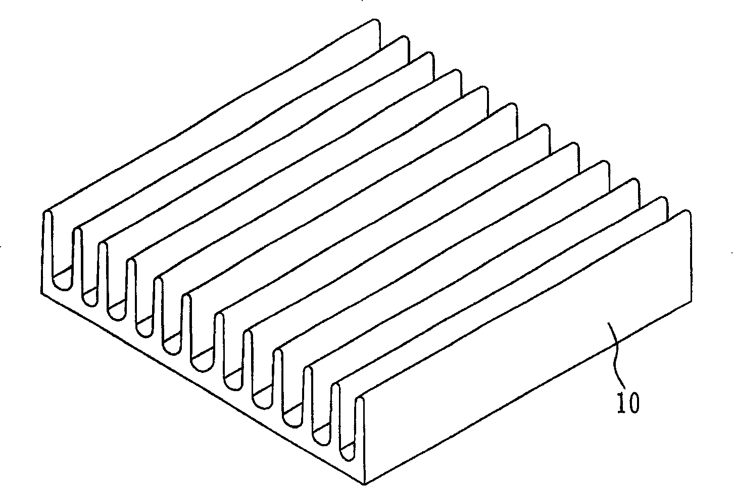
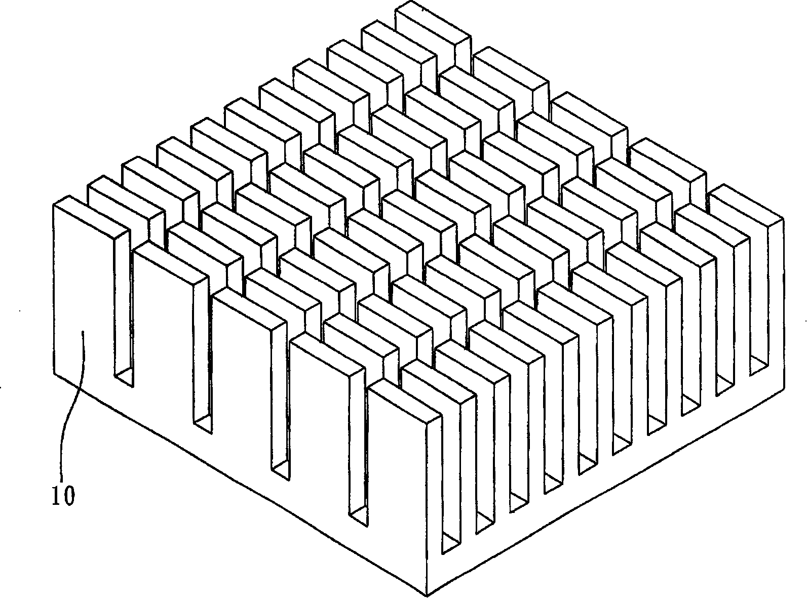
However, the traditional linear heat sink cannot produce effective disturbance, so its heat dissipation effect is really limited
[0005] That is to say, for the heat dissipation fins installed in electronic equipment such as desktop computers or notebook computers, because the heat dissipation fins are in a straight line, the air flow channels formed between the heat dissipation fins, the heat exchange mixing degree between the airflows Low, so that the heat dissipation rate is poor; in addition, the gas flow channel formed by the air between the heat dissipation fins cannot be effectively disturbed to obtain kinetic energy supplement, so that the speed of the airflow in the rear part of the flow channel will slow down, affecting the heat dissipation efficiency

Method used


Image

  • Heat radiation structure
  • Heat radiation structure
  • Heat radiation structure

Examples


Embodiment Construction

[0027] The implementation of the present invention is described below through specific examples, and those skilled in the art can easily understand other advantages and effects of the present invention from the content disclosed in this specification.

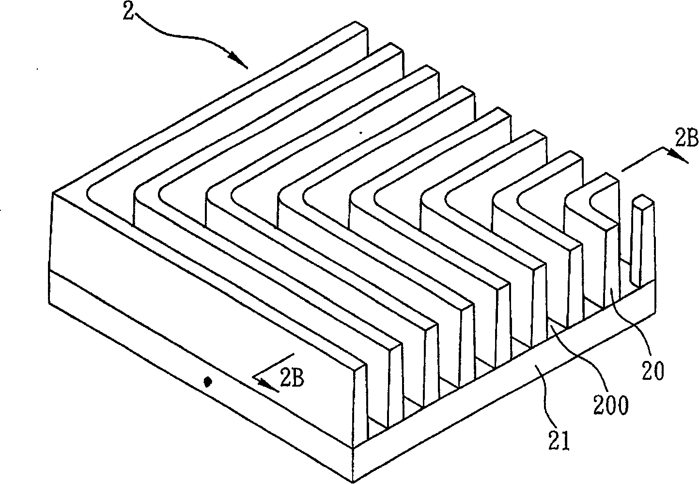
[0028] see Figure 2A and Figure 2B , is a perspective view and a schematic cross-sectional view of a preferred embodiment of the heat dissipation structure of the present invention.

[0029] The heat dissipation structure 2 of the present invention includes a base 21 ; and a plurality of heat dissipation fins 20 combined on the base 21 and arranged at intervals to form passages 200 for air circulation between each heat dissipation fin 20 .

[0030] Such as Figure 2A As shown, the shape of the plurality of cooling fins 20 arranged on the base 21 is in the shape of a broken line, such as the L-shaped right-angled broken line shown in the figure. The L-shaped right-angle channel 200 through which the flow passes.

[0031] P...


PUM


Abstract

The invention discloses a heat dissipation structurewhich comprises a base seat and heat dissipation fins which are combined on the base seat and are arranged in an interval way; wherein, the heat dissipation fins present a folding line shape, the width of one end of each heat dissipation fin which is connected to the base seat is larger than that of the end which is away from the base seat; thus the heat dissipation fins are formed without enlarging the size and weight of the heat dissipation structure, wherein, the outline of each heat dissipation is f folding line-shaped (that is L-shaped) and the section plane thereof is narrow in upper side and wide in lower side (that is trapezoidal), thereby enhancing the destabilization between the air and the wall surfaces of the heat dissipation fins, and improving the heat transfer rate and heat-sinking rate.

Description

technical field [0001] The present invention relates to a heat dissipation structure, more specifically, to a heat dissipation structure used in electronic equipment to dissipate heat energy generated by electronic heating elements. Background technique [0002] The central processing unit (CPU, Central Processor Unit) used to provide computer computing and main control functions is the central part of the computer, and its importance is self-evident. However, the high-frequency operation of the central processing unit will generate high heat, and the high temperature may become a problem for the computer system. The potential crisis of paralysis, so the heat dissipation structure to solve this problem is born in anticipation. [0003] The existing heat dissipation structure for assisting the heat dissipation of the central processing unit is mainly to fix a heat dissipation block on a frame. The screw can pass through the spring and then be locked on the frame. Therefore, ...

Claims


Application Information

Patent Timeline
Patent Type & Authority Applications(China)
IPC IPC(8): H05K7/20H01L23/367G06F1/20
Inventor 白耀忠杨逸民
Owner INVENTEC CORP
Why Eureka
Try Eureka