

Hydrodynamic bearing device and spindle motor using the same
A fluid bearing and carbon number technology, applied in the field of dynamic pressure fluid bearing devices and spindle motors, can solve the problems of insufficient reliability of the device, shortened device service life, low heat resistance of lubricants, etc., so as to improve the evaporation rate. Effects of improved characteristics, device reliability, and high heat resistance
Inactive Publication Date: 2008-07-09
PANASONIC HEALTHCARE HLDG CO LTD
View PDF3 Cites 2 Cited by
- Summary
- Abstract
- Description
- Claims
- Application Information
AI Technical Summary
Problems solved by technology
[0007] However, although the torque of these conventional fluid bearing devices can be reduced, there are problems in that the amount of evaporation is increased due to the low heat resistance of the lubricant, the service life of the device is shortened, and the reliability of the device cannot be sufficiently ensured.
In addition, considering the amount of evaporation of the lubricant, if an excessive amount of lubricant is filled beyond the necessary amount, there are problems such as an increase in torque and an increase in cost, and it is difficult to achieve miniaturization and secure space.
Method used
View moreImage
Smart ImageViewing Examples

Examples
Embodiment 1
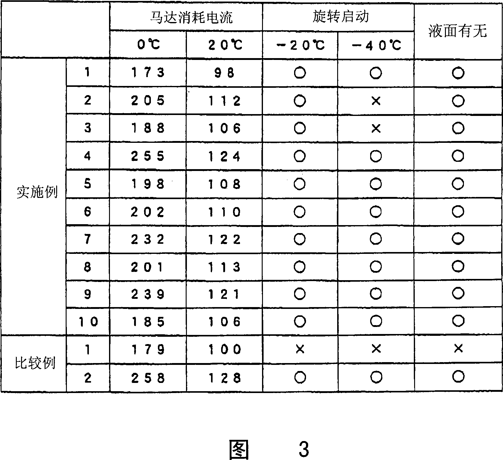
[0090] The diester formed by 3-methyl-1,5-pentanediol and n-nonanoic acid is used as lubricant.
Embodiment 2
[0092] A diester formed of 3-methyl-1,5-pentanediol and n-decanoic acid was used as lubricant.
Embodiment 3
[0094] The diester formed by 3-methyl-1,5-pentanediol and n-nonanoic acid / n-decanoic acid (molar ratio 50:50) was used as lubricant.
Login to View More PUM
 Abstract
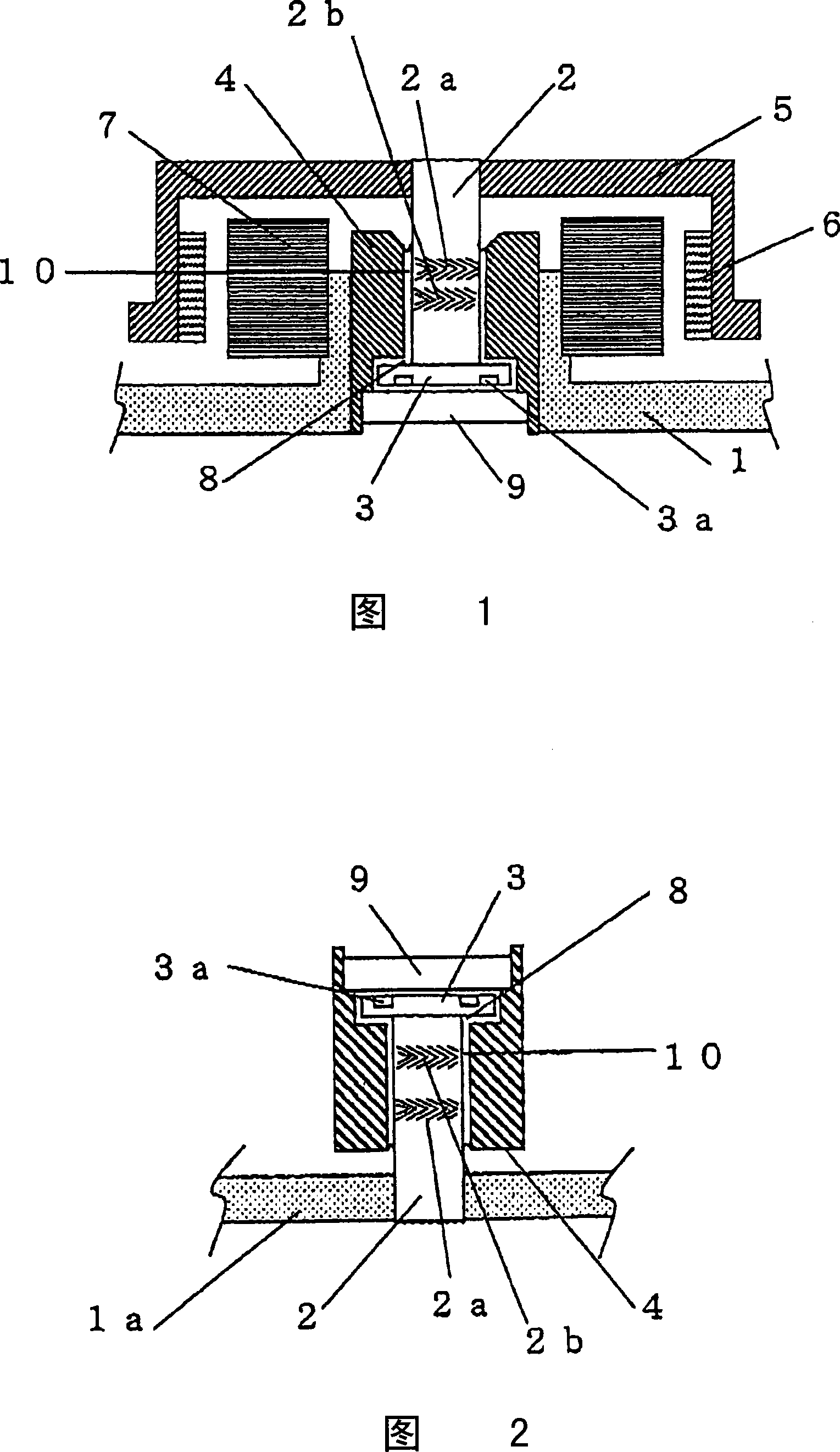
A hydrodynamic bearing device being low in torque, low in power consumption, high in reliability and best suited for miniaturization and a spindle motor using the same. The hydrodynamic bearing device in accordance with the present invention, dynamic pressure generation grooves being provided on at least one of a shaft or a sleeve, and a lubricant being present in a clearance where the above-mentioned shaft and the above-mentioned sleeve are opposed to each other, is characterized in that the above-mentioned lubricant contains diesters obtained from a divalent alcohol having 4 to 8 carbon atoms and having no alkyl side chain at the beta position and one or more kinds of saturated monovalent fatty acids having 9 to 13 carbon atoms.
Description
[0001] This application is a divisional application of the Chinese patent application entitled "Fluid Bearing Device and Spindle Motor Using the Device" with the filing date of March 31, 2005 and the application number of 200510056240.4. technical field [0002] The present invention relates to a dynamic pressure type fluid bearing device and a spindle motor using the same. Background technique [0003] Fluid bearings consist of a shaft and a sleeve supporting the shaft, and lubricant exists in the gap between the two. Through the dynamic pressure generating groove formed in the shaft or the sleeve, as the shaft rotates, the lubricant gathers and generates pressure, and the shaft is supported by the sleeve in a non-contact state. This enables high-speed rotation and reduces noise during rotation. [0004] Spindle motors equipped with this fluid bearing device are being used for information setting and audio-visual equipment represented by magnetic disk devices because they ...
Claims
Login to View More Application Information
Patent Timeline
 IPC IPC(8): F16C17/10F16C33/10C10M105/38C10M105/42C10M169/04C10N30/06C10N40/02C10N40/06H02K7/08
Inventor平田勝志白石孝範大野英明
OwnerPANASONIC HEALTHCARE HLDG CO LTD