Discharge gas and waste heat recovery heat converter

A technology for waste gas waste heat and heat exchangers, which is applied in the direction of heat exchanger types, indirect heat exchangers, lighting and heating equipment, etc. It can solve the problem that the ratio of recovery efficiency to volume is not ideal, which limits the practicability and the degree of technical popularization. Waste heat recovery efficiency and other issues, to achieve the effect of simple and convenient later operation and maintenance, small impact, and high utilization rate

Active Publication Date: 2008-07-09
刘启端
View PDF0 Cites 6 Cited by
  • Summary
  • Abstract
  • Description
  • Claims
  • Application Information

AI Technical Summary

Problems solved by technology

[0002] Existing heat exchangers used in exhaust gas and waste heat recovery have the following disadvantages: 1. The main utilization method of recovered heat is to generate hot water or heat fuel, so that the energy recovered by the system is difficult to recover when the heating equipment is continuously working. Maximum digestion; 2. Existing heat exchangers of this type used for energy exchange between exhaust gas and combustion-supporting gas are not very ideal due to their large volume, heavy weight, complex structure and process, difficult maintenance, and unsatisfactory recovery efficiency and volume ratio Thereby reducing the economy, limiting its practicability and technology promotion
With this structure, although the heat conduction sheet increases the heat dissipation area, it also produces a thermal hysteresis effect, which greatly limits the improvement of waste heat recovery efficiency.

Method used


Image

  • Discharge gas and waste heat recovery heat converter
  • Discharge gas and waste heat recovery heat converter
  • Discharge gas and waste heat recovery heat converter

Examples


Embodiment Construction

[0021] The present invention will be further described below in conjunction with the accompanying drawings.

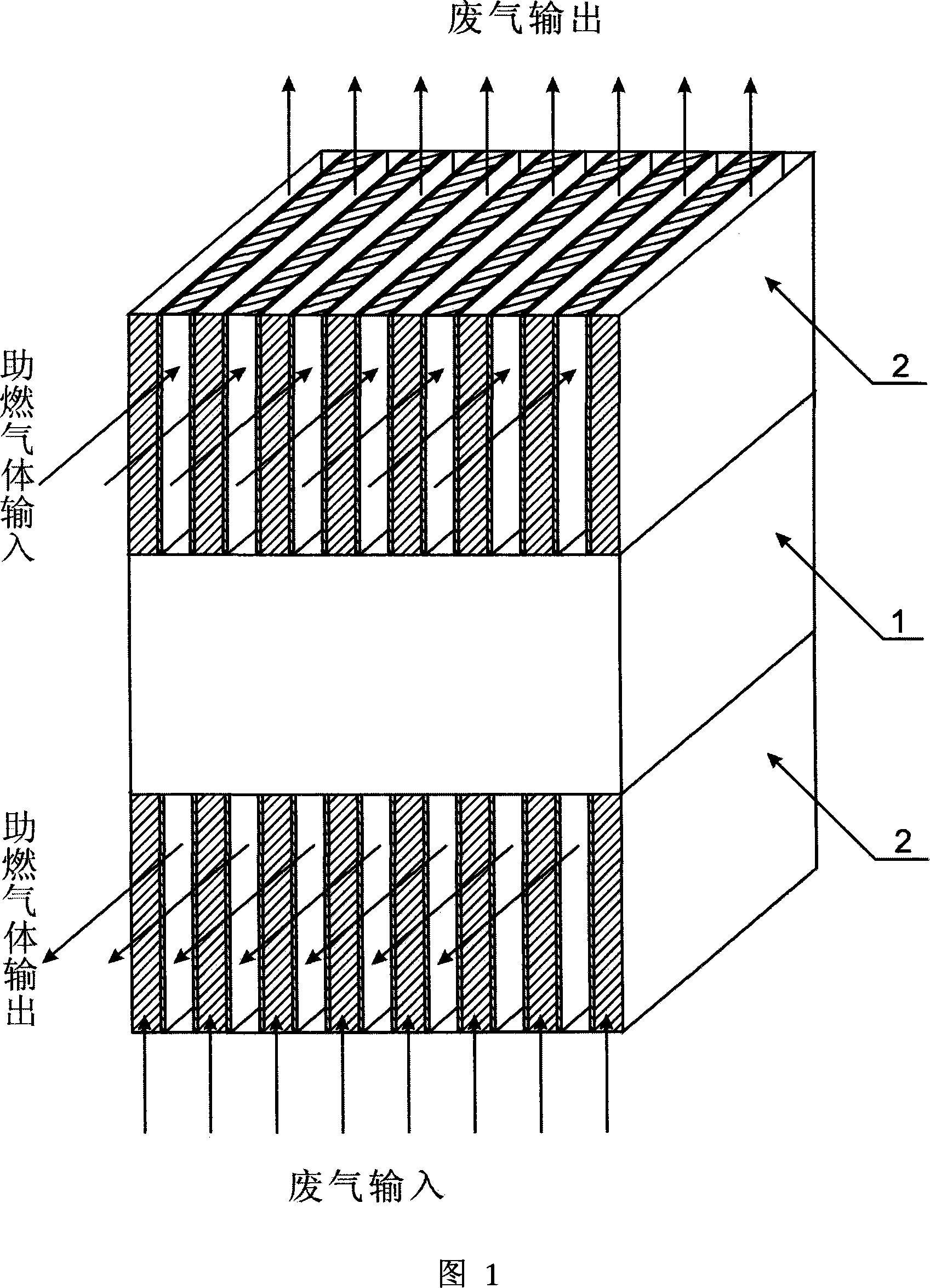
[0022] The basic working principle of the present invention is to preheat the combustion-supporting gas by recovering the heat of the exhaust gas after combustion provided by the waste gas and waste heat recovery heat exchanger provided by the present invention. Since the preheated combustion-supporting gas carries a certain amount of heat into the boiler and industrial furnace, the combustion rate is reduced. The amount of fuel required. At the same time, since the exhaust gas is used to preheat the combustion-supporting gas, the heat loss in the exhaust gas is also reduced, thereby achieving the purpose of environmental protection and energy saving. In addition, the excess combustion-supporting gas after preheating can preheat the product and supplement heat to the equipment, thereby reducing the amount of fuel required for production.

[0023] Fig. 1 is a schematic...


PUM


Abstract

The invention discloses a heat exchanger for recovering exhaust gas and waste heat, which comprises a heat exchanger and a fluid diverter. The heat exchanger comprises a case body and corrugated heat exchange plates. The case body has a cuboid structure with opened up and down end surfaces; the corrugated heat exchange plates are laminated together and fixed inside the case body; and a gas passage is provided between adjacent corrugated heat exchange plates, and the inlet and outlet of the gas passage are provided on one of the opened end surfaces. The fluid diverter comprises a case body and passage partitioning plates; the partitioning plates are parallelly disposed and fixed inside the case body of the fluid diverter to divide the space of case body into an exhaust gas passage and a combustion supporting gas passage; the fluid diverter is installed at the inlet and outlet of the heat exchanger; and the exhaust gas passage and the combustion supporting gas passage are separated from each other. The inventive heat exchanger can recover exhaust gas and waste heat on site; and has the advantages of small volume, light weight, simple structure, remarkably improved unit volume heat exchange efficiency, good reliability, saved energy consumption and environmental friendliness.

Description

technical field [0001] The invention belongs to the field of exhaust gas and waste heat recovery equipment, and in particular relates to a waste gas and waste heat recovery heat exchanger for energy exchange between combustion boilers, industrial furnace waste gas and combustion-supporting gas. Background technique [0002] Existing heat exchangers used in exhaust gas and waste heat recovery have the following disadvantages: 1. The main utilization method of recovered heat is to generate hot water or heat fuel, so that the energy recovered by the system is difficult to recover when the heating equipment is continuously working. Maximum digestion; 2. Existing heat exchangers of this type used for energy exchange between exhaust gas and combustion-supporting gas are not very ideal due to their large volume, heavy weight, complex structure and process, difficult maintenance, and unsatisfactory recovery efficiency and volume ratio Thereby reduced economy, has limited its practic...

Claims


Application Information

Patent Timeline
Patent Type & Authority Applications(China)
IPC IPC(8): F28D9/02
Inventor 刘启端
Owner 刘启端
Why Eureka
Try Eureka