
Reciprocity integrated optical modulation chip for optical fiber gyroscope

A technology of integrated optics and fiber optic gyroscopes, applied in optics, optical components, Sagnac effect gyroscopes, etc. Increase, stability and reliability reduction and other issues, to achieve the effect of improving reliability and environmental performance, avoiding adverse effects, and small size

Inactive Publication Date: 2008-07-09
ZHEJIANG UNIV
View PDF0 Cites 19 Cited by
  • Summary
  • Abstract
  • Description
  • Claims
  • Application Information

AI Technical Summary

Problems solved by technology

[0003] While ensuring the reciprocity of the fiber optic gyroscope, the beam splitter also introduces other problems, such as the performance degradation of the gyroscope caused by the changes in the insertion loss, beam splitting ratio, and extinction ratio with temperature.
The connection between the beam splitter and the Y-waveguide modulator needs to be realized by pigtail fusion, which will increase the loss of the gyro optical system, reduce the stability and reliability, and the manufacturing process is complicated and bulky, which cannot adapt to the high-precision and high-precision fiber optic gyroscope. The development trend of reliability and miniaturization

Method used


Image

  • Reciprocity integrated optical modulation chip for optical fiber gyroscope
  • Reciprocity integrated optical modulation chip for optical fiber gyroscope

Examples


Embodiment Construction

[0022] The present invention will be further described below in conjunction with the accompanying drawings.

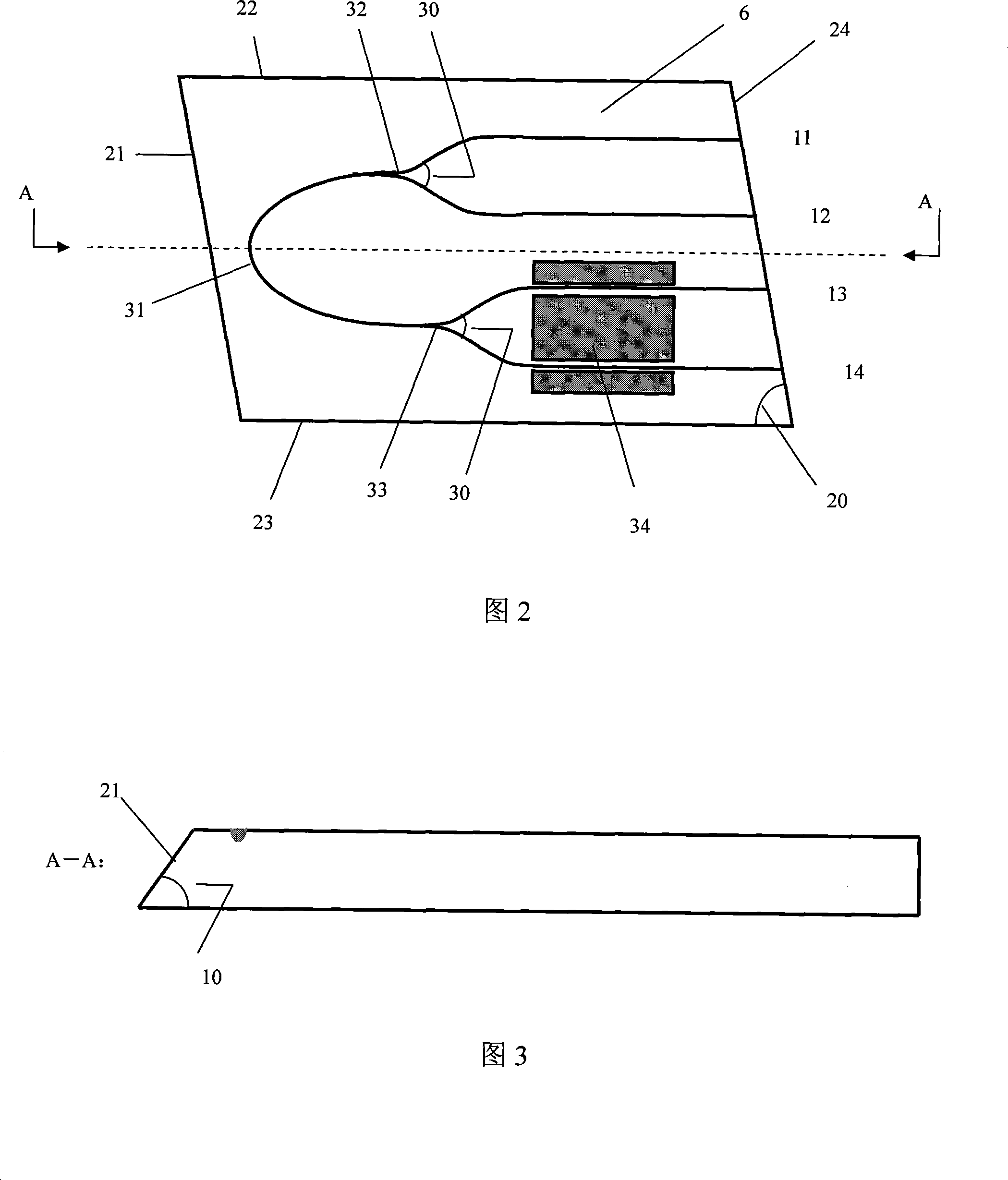
[0023] As shown in Figure 2, the reciprocity integrated optical modulation chip 6 of the present invention comprises two Y branch waveguides 32,33 and an arc waveguide 31, and one end of the arc waveguide 31 is connected with the first Y branch waveguide 32, and the arc waveguide The other end of 31 is connected to the second Y-branch waveguide 33, the two sides of the second Y-branch waveguide 33 are provided with modulator electrodes 34, and the two branch ends of the first Y-branch waveguide 32 are respectively connected to the first port 11 and the second port 12 of the chip , the two branch ends of the second Y-branch waveguide 33 are respectively connected to the third port 13 and the fourth port 14 of the chip, and the chip 6 is surrounded by a reflection radiation mode edge 21, an upper edge 22, a lower edge 23, and a pigtail coupling edge 24 . The width of al...


PUM

PropertyMeasurementUnit
Widthaaaaaaaaaa
Inclinationaaaaaaaaaa

Abstract

The invention discloses a reciprocating integrated optical modulation chip used in an optical fiber gyroscope, which comprises two Y-branching waveguides and an arc-shaped waveguide, wherein one end of the arc-shaped waveguide is connected with a first Y-branching waveguide, the other end of the arc-shaped waveguide is connected with a second Y-branching waveguide, a modulator electrode is respectively disposed at the two sides of the second Y-branching waveguide, the two branching ends of the first Y-branching waveguide are respectively connected with a first port and a second port of the chip, the two branching ends of the second Y-branching waveguide are respectively connected with a third port and a fourth port of the chip, and a reflected radiation film edge, an upper edge, a lower edge and a tail fiber coupling edge are disposed at the circumference of the chip. The integrated optical modulation chip can replace a beam splitter and a Y-waveguide modulator, so as to improve the integration level of the optical system of the optical fiber gyroscope. The invention overcomes the shortcomings of discrete components combination, improves the reliability and environmental performance of the optical fiber gyroscope, is helpful for simplifying the structure of the gyroscope, reduces the space occupation of the system, simplifies the production process of the gyroscope, and can obtain the optical fiber gyroscope with smaller size, high accuracy and high stability.

Description

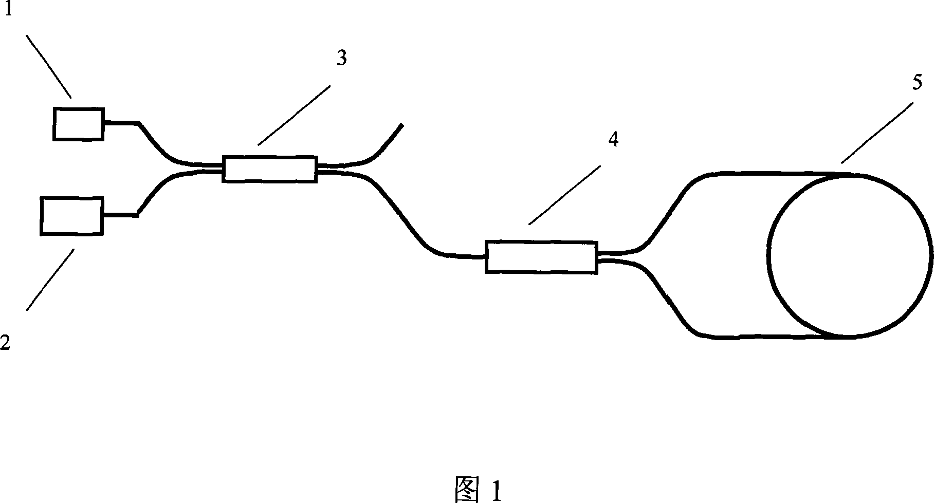
technical field [0001] The invention relates to an integrated optical chip of electro-optical materials, in particular to a reciprocal integrated optical modulation chip for an optical fiber gyroscope. Background technique [0002] Fiber optic gyroscope is a kind of angular velocity fiber optic sensor based on optical Sagnac effect, and it is a high-precision interferometric system integrating light, machinery, electricity and calculation. At present, the optical fiber gyroscope adopts the structure shown in Figure 1, uses discrete devices, and realizes the interconnection between the devices by means of optical fiber fusion to build an optical system. Referring to Figure 1, in the optical system of the fiber optic gyroscope, the light emitted by the light source 1 is divided into two beams through the beam splitter 3 and the Y waveguide modulator 4 successively, enters the fiber optic ring 5 and propagates in the opposite direction, and then passes through the Y-waveguide ...

Claims


Application Information

Patent Timeline
IPC IPC(8): G01C19/72G02B6/125
Inventor 盛芳舒晓武刘承
Owner ZHEJIANG UNIV
Learn More