
Refrigerating method of high-capacity optical fiber laser

A fiber laser and refrigeration method technology, applied in lasers, laser parts, phonon exciters, etc., can solve the problems of unfavorable cooling liquid heat, small contact area between metal and cooling liquid, fiber structure damage, etc., to ensure continuous stability. The effect of running, lowering the temperature

Inactive Publication Date: 2008-07-16
NAT UNIV OF DEFENSE TECH
View PDF0 Cites 12 Cited by
  • Summary
  • Abstract
  • Description
  • Claims
  • Application Information

AI Technical Summary

Problems solved by technology

Document 3 proposes a cooling device for the output end of a high-power double-clad fiber laser. The optical fiber needs to be placed in the fiber groove milled on the metal sleeve. The air medium is introduced in between, which reduces the cooling effect; if the size of the fiber groove is smaller than the size of the fiber, it is easy to cause damage to the structure of the fiber, and there is only one coolant inlet and outlet tube in the metal sleeve, and the contact area between the metal and the coolant is small. It is beneficial for the cooling liquid to take away a large amount of heat; at the same time, the design idea of ​​Document 3 is limited to a single high-power fiber laser, and does not discuss the cooling problem of a hundred-kilowatt (above) high-energy laser system composed of a high-power fiber laser array
Document 4 discusses and analyzes hundreds of kilowatt-level (above) high-energy laser systems composed of chemical, gas, and solid-state lasers, but does not analyze high-energy laser systems composed of high-power fiber laser arrays

Method used


Image

  • Refrigerating method of high-capacity optical fiber laser
  • Refrigerating method of high-capacity optical fiber laser
  • Refrigerating method of high-capacity optical fiber laser

Examples


Embodiment Construction

[0019] The present invention will be further described below in conjunction with the accompanying drawings and implementation examples.

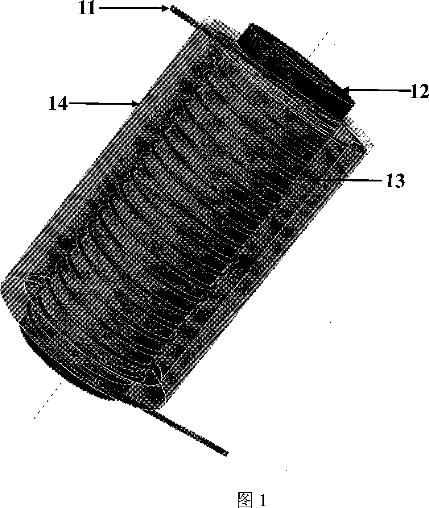
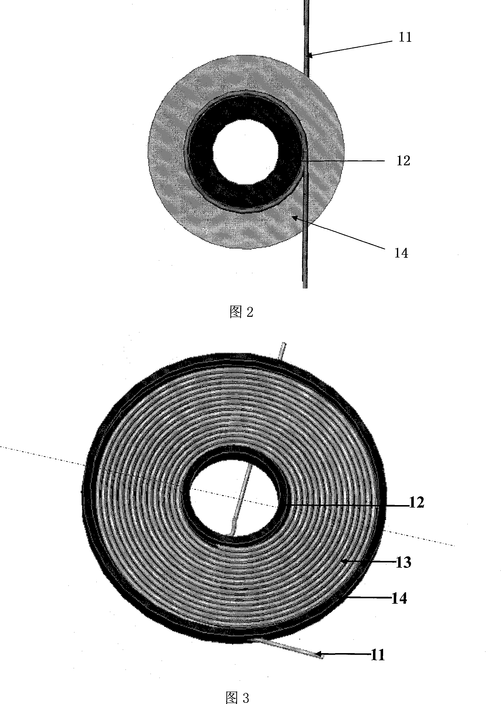
[0020] Fig. 1 is a structural diagram of the refrigeration method for a single high-power fiber laser of the present invention. It can be seen from the figure that the specific implementation structure of the refrigeration method for a single high-power fiber laser of the present invention is that the fiber laser 11 is wound on a metal tube 12 in a single layer and placed on Inside the metal sleeve 14 with coolant channels, the space between the fiber laser 11 and the metal sleeve 14 is filled with emulsion liquid or solid powder 13 . Both the inside of the metal pipe 12 and the cooling liquid channel adopt the flowing cooling liquid to take away the heat in time. Fig. 2 is a structural top view of the refrigeration method for a single high-power fiber laser of the present invention.

[0021] The cooling liquid may be cooling water or other...


PUM


Abstract

The invention relates to a refrigeration method for a high-power fiber laser and a high-power fiber amplifier. The method is carried out by use of a fiber laser, emulsus liquid or solid powder, a metal sleeve provided with a cooling passage, a metallic conduit and so on; an optical fiber is wound on the metallic conduit and positioned inside the metal sleeve provided with the cooling passage; a gap between the optical fiber and the metal sleeve is filled with the emulsus liquid or the solid powder of a high coefficient of heat conduction; the insides of both the metallic conduit and the cooling passage adopt a method of using flow cooling fluid to take away heat generated by the running high-power fiber laser; therefore, an extramural cladding and end faces of the optical fiber are not damaged by heat, and continuous steady operation of the high-power fiber laser is guaranteed.

Description

technical field [0001] The invention relates to a refrigeration method for a high-power fiber laser and a high-power fiber amplifier. Background technique [0002] Fiber lasers are lasers that use doped fibers as the laser medium. It obtains the laser output of the corresponding band by doping different rare earth ions in the fiber matrix material. For conventional single-mode fiber lasers, the pump light injected into the fiber core must also be single-mode, which limits the efficiency of pump light into the fiber, resulting in low output power and efficiency of fiber lasers. The concept of double-clad fiber was proposed in the late 1980s, which provided an effective technical way to improve the output power and conversion efficiency of fiber lasers, and changed the history that fiber lasers can only be used as a low-power optical device. With the development of double-clad fiber manufacturing technology and high-power semiconductor laser pumping technology, the output po...

Claims


Application Information

Patent Timeline
IPC IPC(8): H01S3/042
Inventor 许晓军郭少锋刘亮周朴王鹤陈子伦陈金宝刘泽金
Owner NAT UNIV OF DEFENSE TECH
Learn More