
Distributed soldering point quality monitoring system and method

A technology of solder joint quality and monitoring system, applied in general control system, control/adjustment system, program control, etc., can solve the influence of splash and flare on the accuracy of measurement signal, the linearity of electrode displacement cannot be guaranteed, and it cannot meet distributed requirements. Welding torch spot welding quality and other issues, to achieve the effect of strong bus error correction, good real-time performance, and guaranteed reliability

Inactive Publication Date: 2008-07-23
SHANGHAI JIAO TONG UNIV
View PDF1 Cites 30 Cited by
  • Summary
  • Abstract
  • Description
  • Claims
  • Application Information

AI Technical Summary

Problems solved by technology

But there are the following disadvantages: 1. The laser displacement sensor is expensive, and the accuracy of the measurement signal is easily affected by the spattering of the fire during on-site welding, which affects the correctness of the quality evaluation of the solder joints; 2. Due to the limitation of the pneumatic welding torch position, it is not All stations can be equipped with displacement sensors to collect dynamic electrode displacement. For example, for welding torches with long X-type electrode arms, not only must special fixtures be made to fix the sensors, but also the linearity of measured electrode displacement cannot be guaranteed; 3. The device can only detect the quality of solder joints at a single station, without the bus communication function, and cannot meet the needs of detecting spot welding quality of distributed welding guns on site

Method used


Image

  • Distributed soldering point quality monitoring system and method
  • Distributed soldering point quality monitoring system and method

Examples


Embodiment Construction

[0021] The embodiments of the present invention will be described in detail below with reference to the accompanying drawings: this embodiment is implemented on the premise of the technical solution of the present invention, and detailed implementation modes and specific operating procedures are given, but the scope of protection of the present invention is not limited to the following Mentioned examples.

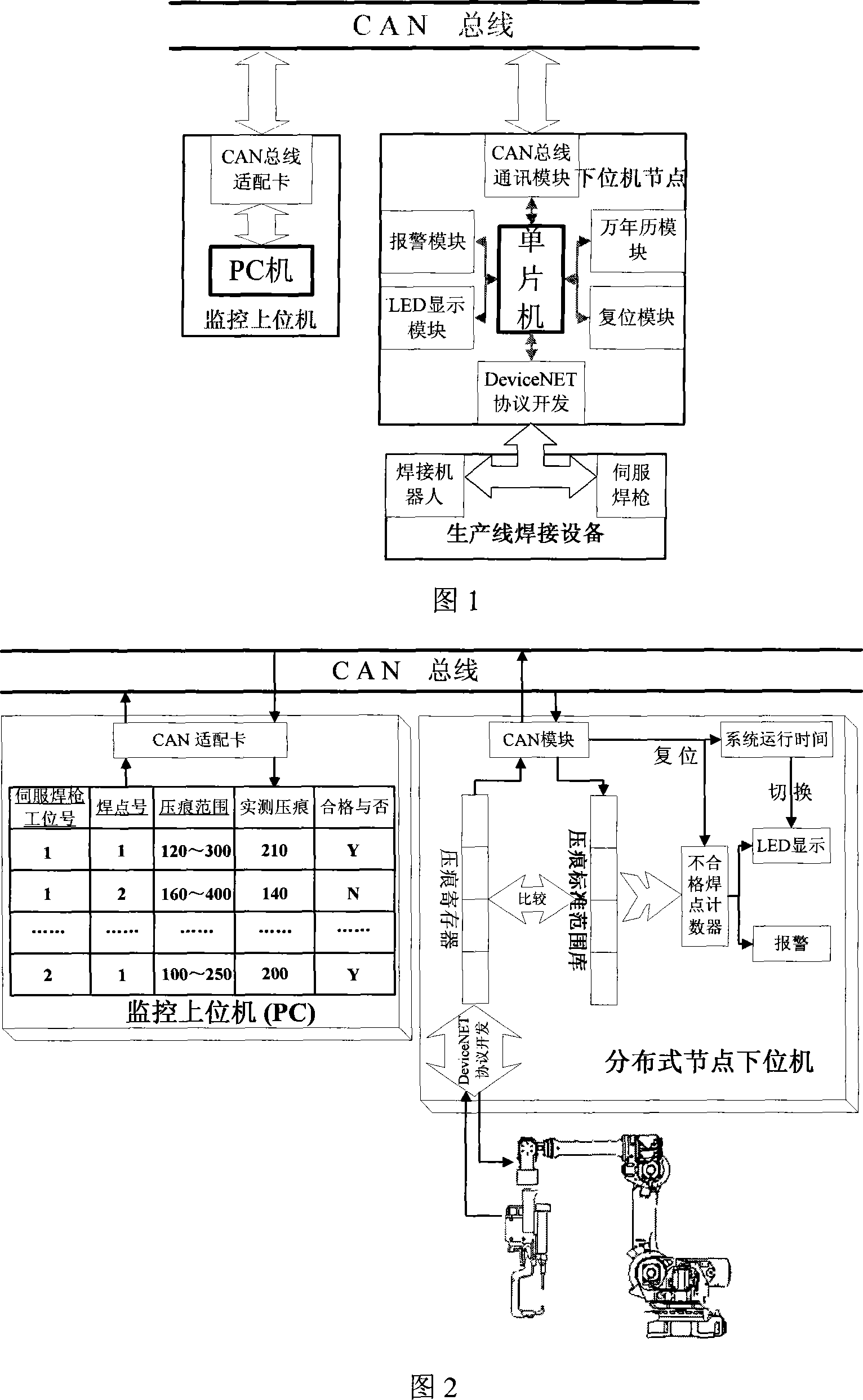
[0022]As shown in Figure 1, the distributed solder joint quality monitoring system system of this embodiment includes: monitoring upper computer, CAN bus, distributed node lower computer, including: monitoring upper computer, CAN bus, distributed node lower computer, where : The monitoring host computer includes a PC and a CAN bus communication adapter card. The PC is connected to the CAN bus communication adapter card through the PCI interface. The CAN bus communication adapter card is connected to each distributed node and the lower computer through the CAN bus. The node lowe...


PUM


Abstract

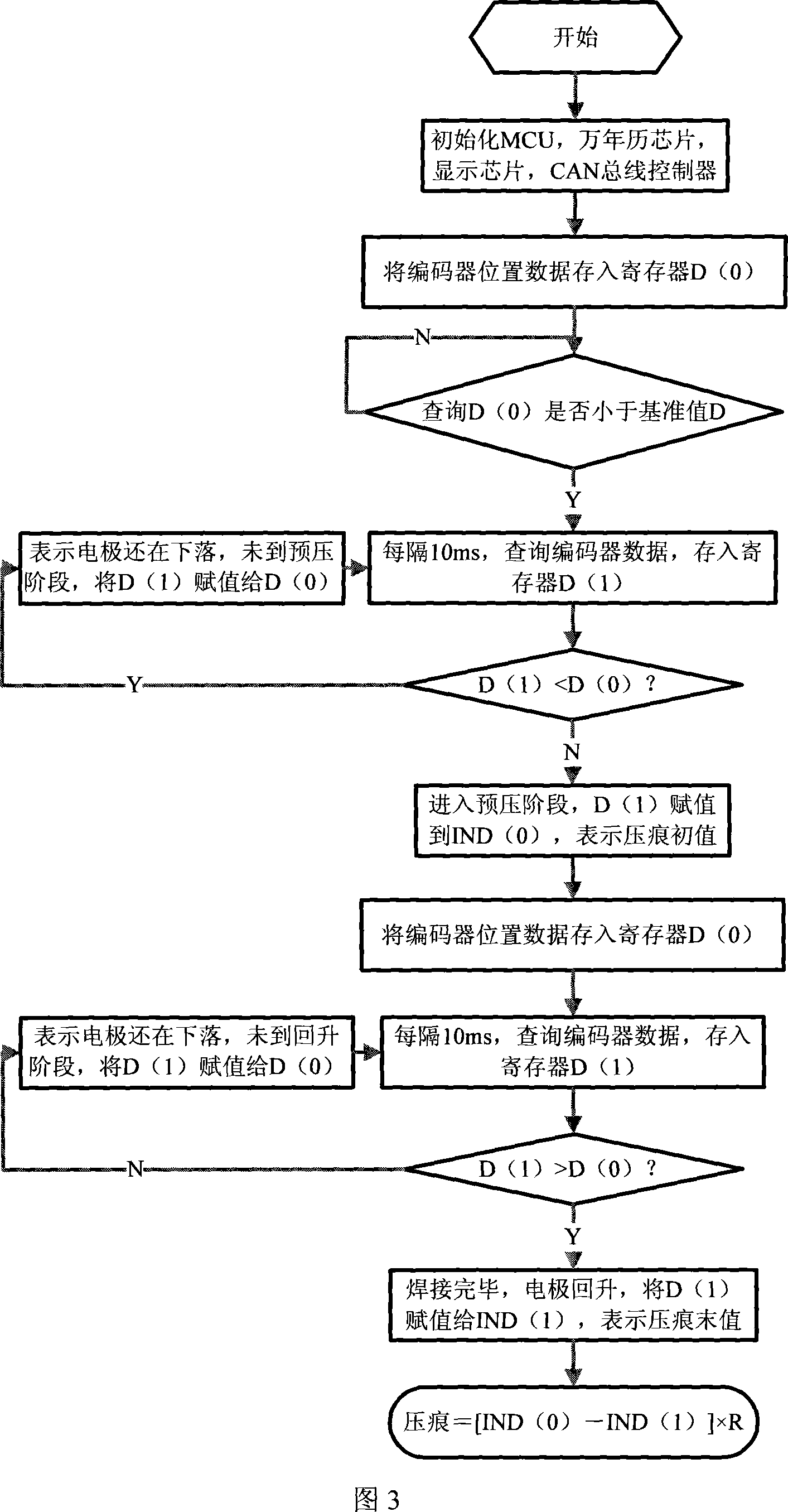
The invention relates to a distribution welding point quality detection system and a relative method, belonging to welding technical field. The system comprises a detection host computer, a controller local network bus and a distribution node lower computer, wherein the detection host computer comprises a PC and a controller local network bus communication adaptive card which are connected via a PCI interface, the controller local network bus communication adaptive card is connected with each distribution node lower computer via a controller local network bus. The inventive method comprises that each lower computer online real-time extracts the impression of welding point to be sent to the controller local network bus, the PC sends the welding point match change information caused by the change of servo welding gun position to a lower computer of relative ID number, real-time refreshes the standard base of the distribution node lower computer that judges the welding point, and returns the off-grade welding point counter. The inventive system and method have high reliability, strong bus correct function, better real-time property, remote transmission distance and better expansibility.

Description

Technical field [0001] The invention relates to a system and method in the field of welding technology, in particular to a distributed welding spot quality monitoring system and method based on a controller local area network bus. Background technique [0002] At present, resistance spot welding is still the most important connection method in car body-in-white assembly, completing about 90% of the body assembly work. Usually a car body-in-white has 3000-5000 solder joints, and the quality of the solder joints directly affects the body. Due to its safety and reliability and assembly deviation, online real-time inspection of solder joint quality is of great significance to the automotive industry. When using traditional pneumatic welding torches to weld thin body plates, since the pneumatic welding torch is open-loop controlled, it cannot provide real-time feedback of any information that characterizes the quality of the solder joints during the welding process. Therefore, offline...

Claims


Application Information

Patent Timeline
IPC IPC(8): G05B19/418G05B19/048B23K11/11
CPCY02P90/02
Inventor 林忠钦来新民陈关龙张延松张小云
Owner SHANGHAI JIAO TONG UNIV
Learn More