
Optical forceps based on ring -shaped multi- core optical fibre

A multi-core optical fiber and single-core optical fiber technology, applied in the field of optical tweezers, can solve the problems of unfavorable living micro-life research, small capture force, and elevated temperature

Inactive Publication Date: 2008-08-06
HARBIN ENG UNIV
View PDF1 Cites 59 Cited by
  • Summary
  • Abstract
  • Description
  • Claims
  • Application Information

AI Technical Summary

Problems solved by technology

For example, the trapping force formed by particles in the light field formed by the strong focusing of a single beam is small. To increase the trapping force, the optical power must be increased, and the higher optical power density will lead to The local liquid temperature rises, which is not conducive to the study of living micro life

Method used


Image

  • Optical forceps based on ring -shaped multi- core optical fibre
  • Optical forceps based on ring -shaped multi- core optical fibre
  • Optical forceps based on ring -shaped multi- core optical fibre

Examples


Embodiment Construction

[0022] The present invention is described in more detail below in conjunction with accompanying drawing example:

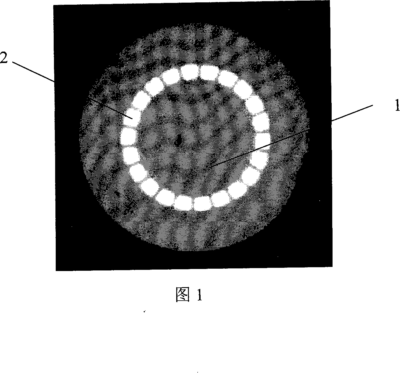
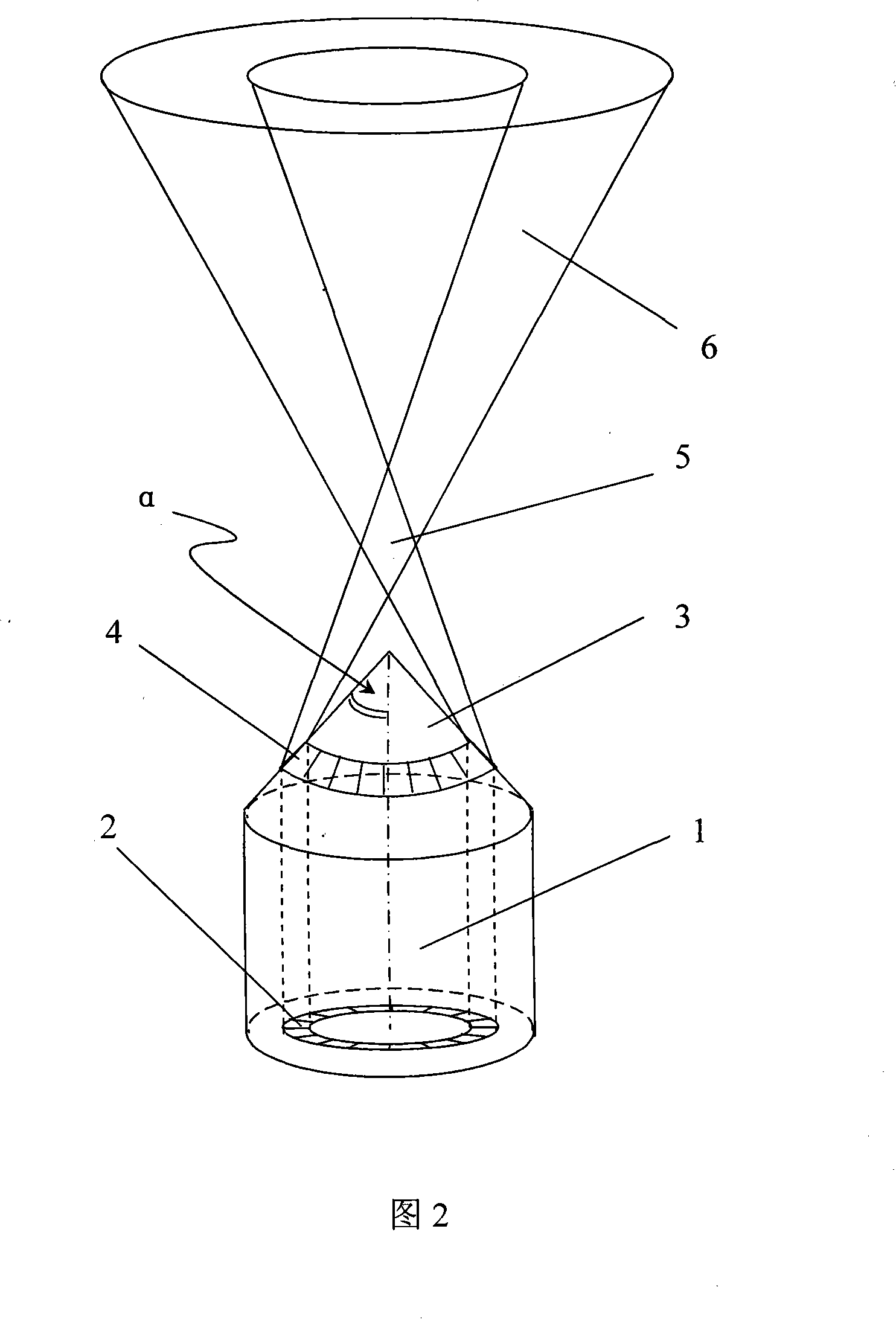
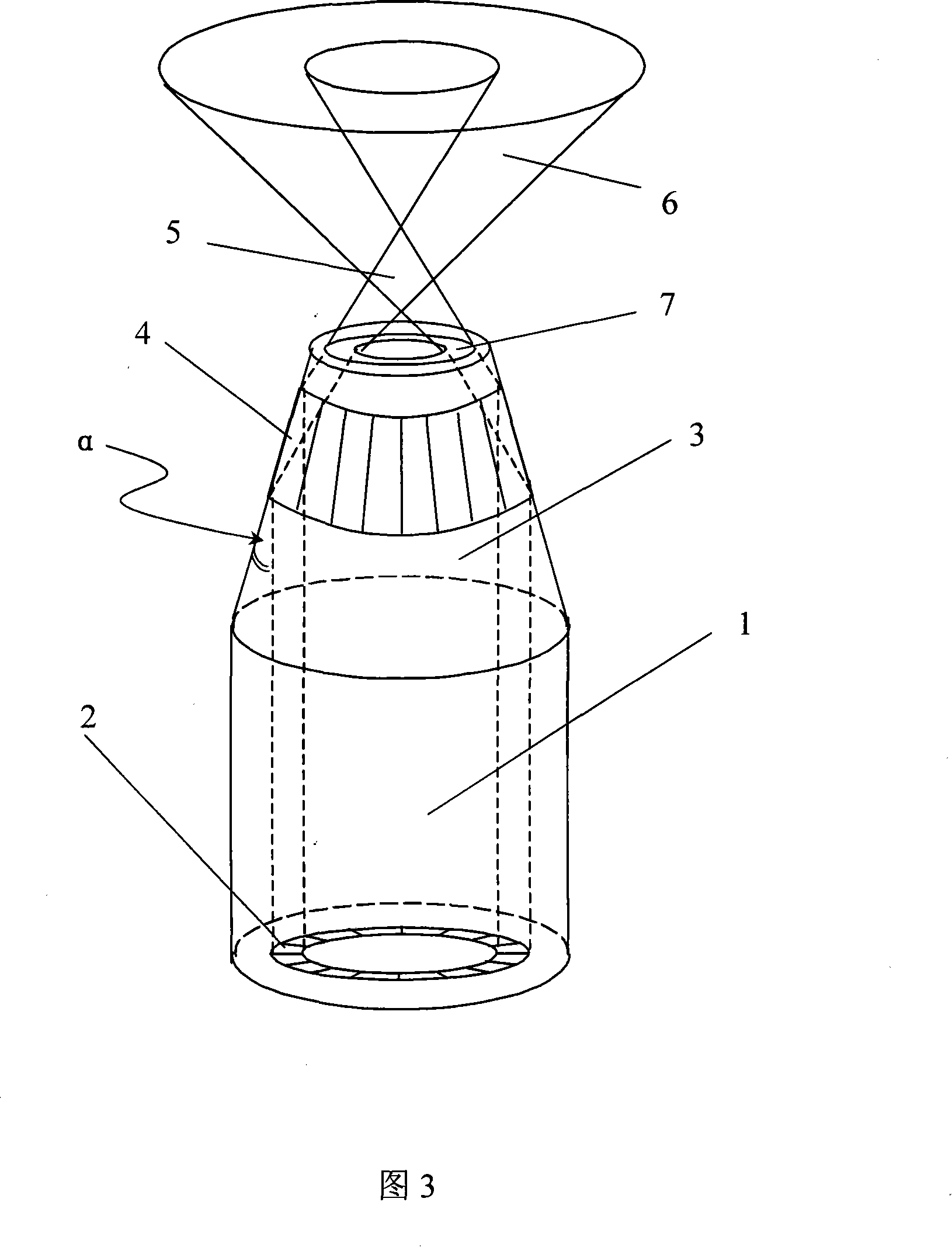
[0023] In conjunction with Fig. 2, the first embodiment of the present invention includes an optical fiber, and the optical fiber includes an optical fiber with an annular multi-core structure and a single-core optical fiber coupled and connected to the tail end of the three-core optical fiber, and the front end of the optical fiber with an annular multi-core structure passes through The method of grinding and processing the fiber end is made into a cone. The cone is formed by grinding the fiber end, and the conical half cone angle α is controlled at π / 2-arcsin(n liquid / n core )<α<π / 2. Its specific implementation process is as follows:

[0024] Step 1, cone grinding: take a section of annular multi-core optical fiber as shown in Figure 1, wherein 1 is an optical fiber with an annular multi-core structure; 2 is an optical fiber core in an annular distribution s...


PUM


Abstract

The invention provides optical tweezers based on a ring-shaped multi core fiber which comprise an fiber with a ring-shaped multiple core structure and a single-core fiber which is in coupled connection with the rear of the ring-shaped multiple core fiber and is connected with a light source, wherein the front end of the fiber with a ring-shaped multiple core structure is manufactured and made into a cone or a cone round table shape by grinding the ends of the fiber or is manufactured and made into a gradient cone round table shape by cutting the sharp ends after heating and applying fusing and tapering. The optical tweezers have the main advantage of large three dimensional trapping force, and thereby for tiny particles in the same size , the optical tweezers do not need high power of light source to realize three dimensional operation, which not only greatly reduces the impact on intravital micro-life due to raised temperature at the optical tweezers point end led by the light source, but also weakens the disturbance on the captured tiny particles by a local thermal convection, reducing the cost of the system and improving the stability of the system.

Description

(1) Technical field [0001] The invention relates to an optical tweezers, in particular to an optical fiber optical tweezers made on the basis of annular multi-core optical fibers. (2) Background technology [0002] Optical tweezers are tools that use the gradient force and light scattering force of light intensity distribution to capture and manipulate tiny particles. Since 1986, Askin (A.Ashkin, J.M.Dziedzic, J.E.Bjorkholm, and S.Chu, Observation of a single-beam gradient force optical trap for dielectric particles, Opt.Lett.11, 288-290, 1986) introduced single beam laser After the high numerical aperture objective lens forms a three-dimensional optical potential well and realizes the three-dimensional space control of particles, the optical tweezers technology has rapidly developed into an important research technology, and has promoted the rapid development of several interdisciplinary fields. For example, it has been widely used in the fields of capturing and transporti...

Claims


Application Information

Patent Timeline
IPC IPC(8): G02B6/036G02B6/255G01N15/00G01N37/00G21K1/00
Inventor 苑立波戴强田风军张涛
Owner HARBIN ENG UNIV
Learn More