
Energy feedback and harmonic wave passive compensation system applicable to commutation device

A technology of energy feedback and rectification device, which is applied in the directions of reactive power compensation, reactive power adjustment/elimination/compensation, output power conversion device, etc. problems, to achieve good economic and social benefits, increase realizability and reliability, and improve energy utilization

Inactive Publication Date: 2008-08-06
HUAZHONG UNIV OF SCI & TECH
View PDF1 Cites 21 Cited by
  • Summary
  • Abstract
  • Description
  • Claims
  • Application Information

AI Technical Summary

Problems solved by technology

[0006] 3. If you switch to pwm rectification, you can get a good filtering effect, but its disadvantages are as follows: 1) Most systems currently use non-rectification systems. If a large-scale use of controllable PWM rectification replaces diode uncontrollable rectification, This approach is not realistic in practical applications; 2) In a high-power circuit system, if a controllable PWM rectifier is used instead of a diode rectifier, the fully controlled power switch tube needs a large capacity and high cost. Moreover, it is very difficult to implement, so it is not practical to use this method of controllable PWM rectification to comprehensively solve the problems existing in the diode rectification system.
Although this method is simple, it has the following disadvantages: 1) a large amount of electric energy is consumed in vain, and the operating efficiency of the system is low; The consumption of braking cannot timely suppress the pumping voltage generated by rapid braking, which is not conducive to the further improvement of the overall performance of the system
[0008] Chinese patent document CN1274977A disclosed a "comprehensive power filtering device composed of active and passive components" on November 29, 2000. This device uses active filtering and passive filtering to perform harmonic compensation, but it cannot The energy is fed back, and the structure is complex

Method used


Image

  • Energy feedback and harmonic wave passive compensation system applicable to commutation device
  • Energy feedback and harmonic wave passive compensation system applicable to commutation device
  • Energy feedback and harmonic wave passive compensation system applicable to commutation device

Examples


Embodiment Construction

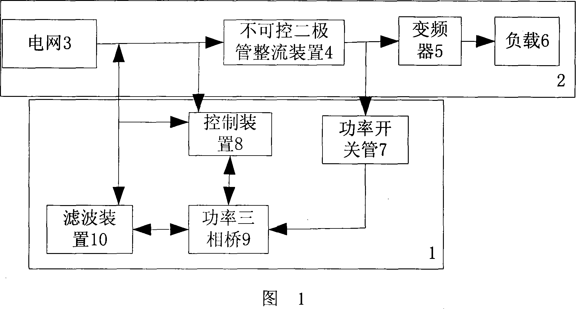
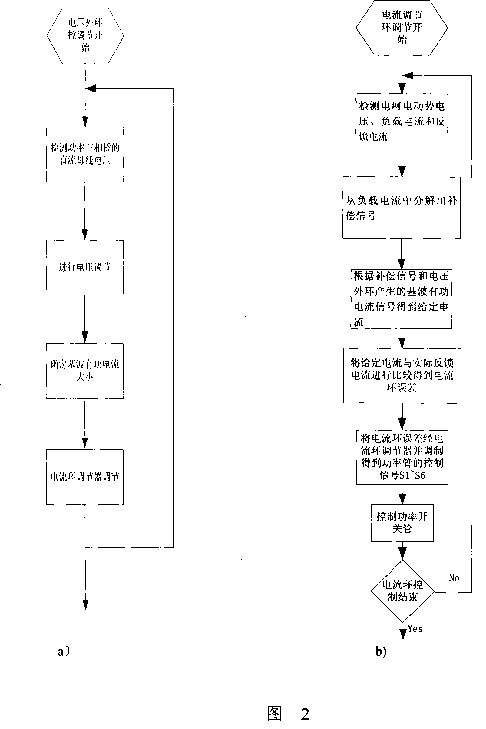
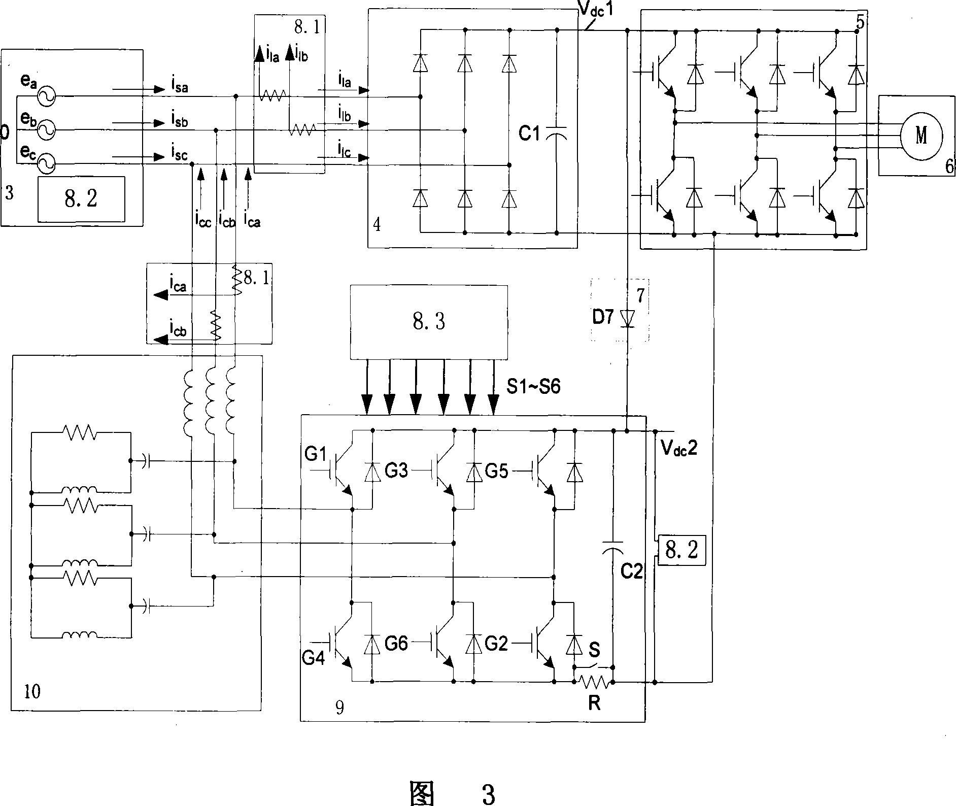
[0023] The system of the present invention will be described in further detail below in conjunction with the accompanying drawings.

[0024] The rectification device applicable to the system of the present invention is connected sequentially by the power grid 3 , the frequency converter 5 of the uncontrollable diode rectification device and the load 6 one by one.

[0025] As shown in FIG. 1 , the energy feedback and harmonic reactive power compensation system of the present invention includes a power switch tube 7 , a control device 8 , a power three-phase bridge 9 and a filter device 10 . The negative output terminal of the diode rectified DC bus voltage is connected to the negative output terminal of the DC bus voltage of the system in this case.

[0026] The anode of the power switch tube 7 is connected to the positive output end of the DC bus voltage of the uncontrollable diode rectifier 4, and its negative pole is connected to the positive pole of the DC bus voltage of th...


PUM


Abstract

The invention discloses an energy feedback and harmonic passive power compensation system applicable to a rectifying device, comprising a power transistor, a controlling device, a three-phase power bridge and a filtering device, wherein, the anode of the power transistor is connected with the anode of a diode rectifying DC voltage, and the cathode of the power transistor is connected with the anode of a DC bus voltage of the three-phase power bridge; the cathode of a diode rectifying DC bus voltage is connected with the cathode of a DC voltage of the three-phase power bridge; the controlling device is used to control the opening and cutting of a power transistor of the three-phase power bridge; the three-phase power bridge is used to provide DC bus voltage to the controlling device and control the closing of the power transistor according to a command from the controlling device to generate a compensation current and provides the compensation current to the filtering device; the filtering device receives the compensation current from the three-phase power bridge, compensates the compensation current to the power grid after filtering high harmonics and provides the current signals to the controlling device. The energy feedback and harmonic reactive power compensation system can play the roles of active filtering and passive compensation, feed back energy to the power grid and realize energy saving.

Description

technical field [0001] The technology of the present invention relates to the technical fields of electric engineering, electronics and electric drive, and in particular to an energy feedback and harmonic reactive power compensation system suitable for rectification devices. Background technique [0002] In the field of electrical and electronic technology, diode rectification circuits are simple, economical and reliable, so they are widely used in most current power electronics and power transmission systems; however, the wide use of rectifiers in this diode rectification circuit also brings the following Aspects of the problem: [0003] Refer to "Power Electronics Technology" published by Machinery Industry Press, which mentions the following shortcomings of diode rectification: [0004] 1. Diode rectification will seriously distort the grid-side current waveform, resulting in low power factor, the highest power factor is only about 0.8; the consumption of a large amount ...

Claims


Application Information

Patent Timeline
Patent Type & Authority Applications(China)
IPC IPC(8): H02M1/42H02J3/18
CPCY02B70/10Y02E40/30
Inventor 沈安文徐金榜
Owner HUAZHONG UNIV OF SCI & TECH
Learn More