Biogas slurry pipeline fertilizing device

A fertilization device and pipeline technology, which is applied in the field of biogas slurry pipeline fertilization equipment, can solve the problems of pipe burst, common water pumps are easy to block, corrode, etc., and achieve the effects of reducing production management costs, facilitating control of biogas slurry concentration, and low pipeline construction and installation costs

Inactive Publication Date: 2008-08-13
熊棣文
View PDF0 Cites 7 Cited by
  • Summary
  • Abstract
  • Description
  • Claims
  • Application Information

AI Technical Summary

Problems solved by technology

Some enterprises adopt dry and thin separation, which only reduces the discharge of excrement and sewage, but cannot fundamentally solve the problem of environmental pollution caused by excrement discharge. Moreover, open-air fermentation of dry excrement, land occupation problems, odor, mosquitoes and flies pollute the environment, feces Problems such as excessive heavy metal pollution in China are difficult to solve
Some enterprises use ordinary irrigation pipes after biogasification of farm manure, but because the biogas slurry contains a lot of chemical substances that will corrode the pipes, ordinary water pumps are easy to block, and the secondary fermentation of the biogas slurry in the pipeline will cause the pipe to burst. Impurities such as biogas residues and microorganisms will also cause corrosion and blockage through the pipeline, so it is difficult to effectively use the biogas slurry
All use mobile irrigation hoses, which are not suitable for large and medium-sized breeding farms, and the hoses have a limited service life and are prone to damage and leakage. Excessive leakage will lead to deterioration of the working environment, and residual liquid pollution in the pipeline will affect pipeline collection.
[0003] At present, there is no system device for returning farm manure to the field

Method used


Image

  • Biogas slurry pipeline fertilizing device

Examples


Embodiment

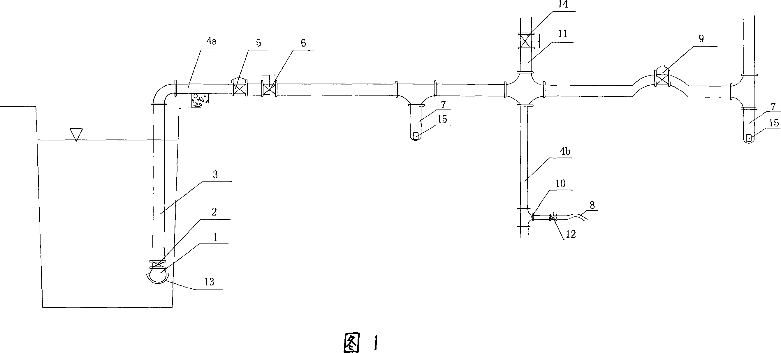
[0015] Embodiment: As shown in Fig. 1, a kind of biogas slurry pipeline fertilization device suitable for farming manure returning to the field includes a submersible sewage pump 1 placed in the lower part of the liquid storage tank, and the suction port of the sewage pump is 10 meters away from the bottom of the liquid storage tank. The distance is 500-800mm; the filter screen 13 coated on the sewage pump 1; the check valve 2 arranged above the submersible sewage pump; the liquid inlet pipe 3 connected with the check valve 2; The main pipeline 4a that the liquid inlet pipe 3 communicates; the quick release valve 5 and the gate valve 6 installed on the main pipeline 4a; the branch pipeline 4b that communicates with the main pipeline 4a; the main pipeline 4a and the branch pipeline 4b The diameter is not less than 50mm; the water outlet pile 10 connected with the branch pipe 4b, the diameter of the water outlet pile 10 is between 25-50mm, and the length is 200-300mm; the control...


PUM


Abstract

The invention relates to a biogas liquid pipeline fertilization device, which includes waste water disposal pump placed at the bottom part of the biogas liquid storage pool, the inverted valve which is placed above the immersed type waste water disposal pump, the liquid inlet tube which is connected to the inverted valve, the main tube which is connected to the liquid inlet tube, the fast pressure-relief valve and gate valve which are installed on the main tube, many branch tubes which are connected to the main tube, the water outlet pile which is connected to the main tube or the branch tube, the control valve which is fixed on the said water outlet pile, the soft tube which is connected to the water outlet pile, the deposit collecting tubes which are installed at the bottom part and the right angle corner of the main tube and branch tubes, the outlet valve which are installed on the said main tube and the branch tubes. The biogas liquid pipeline fertilization device can fertilize the field, which is good for environmental protection, and has the advantages of low cost and long lifespan.

Description

technical field [0001] The invention relates to a pipeline fertilization device for biogas slurry, in particular to a pipeline fertilization device for returning breeding manure to the field. Background technique [0002] Large-scale farming will produce a large amount of manure, which has a negative impact on the environment, and has caused harm to the rural environment, drinking water sources and agricultural ecology. Because manure contains a large amount of short fibers, it is difficult to transport through pipelines. It is mainly picked up and applied by human and animal power. The traditional method of use is high in cost, complicated in use, and low in efficiency. It is difficult to digest the manure produced by large-scale farming. High-quality organic fertilizers often It can only be discarded and cause environmental pollution. On the other hand, the planting industry must use a large amount of chemical fertilizers, making it the largest source of rural non-point s...

Claims


Application Information

Patent Timeline
Patent Type & Authority Applications(China)
IPC IPC(8): A01C23/00A01G25/00
CPCY02P60/21
Inventor 熊棣文熊伟
Owner 熊棣文
Why Eureka
Try Eureka