
Motor drive motor coach hydraulic steering system and controlling steering method thereof

A motor-driven, steering system technology that is applied to automatic steering control components, electric steering mechanisms, steering mechanisms, etc., and can solve problems such as the difficulty in accurately judging steering, the inability to adjust and control the output hydraulic oil flow rate of the oil pump, and the small size of the steering oil pump. , to achieve fast and stable hand feel or dynamic response, to have both hand feel and dynamic response, and to meet the steering performance requirements

Inactive Publication Date: 2008-08-13
JIANGSU UNIV
View PDF2 Cites 47 Cited by
  • Summary
  • Abstract
  • Description
  • Claims
  • Application Information

AI Technical Summary

Problems solved by technology

[0003] (1) For a given hydraulic power steering system, due to the use of engine power to drive, the output hydraulic oil flow of the oil pump cannot be adjusted and controlled. If the designed oil flow is large, it can meet the portability requirements at low speeds, but this will cause The hand feeling becomes worse at high speed, and vice versa when the oil flow rate is small, which makes it difficult to coordinate the contradiction between the lightness and feel of the steering system; if the oil flow rate is large, it can meet the requirements of fast dynamic response during fast steering, but it will cause stability. If the oil flow rate is small, the opposite is true, so it is difficult to coordinate the contradiction between the stability and rapidity of the dynamic response;
[0004] (2) There is energy loss, because it is driven by engine power, even if it is not turning, the oil pump is always working at high speed under the drive of the engine, which increases energy consumption;
[0005] (3) Usually, the bus adopts the layout of the rear engine, and the steering gear is on the front axle, so the layout of the steering system is inconvenient
But it is only an open-loop control system, which does not consider the driver's force input or angle input. At the same time, it judges whether to turn according to the change of the motor current, so that when the vehicle is driving at high speed, the ground resistance is very small, which is very important for accurately judging the steering. It is difficult, and there are only two control modes, that is, the car is running straight and turning, which is difficult to meet the requirements of the complex steering conditions of the vehicle
The U.S. Patent Office No.7164978 has made a major improvement to make this steering system more mature. It uses a vehicle speed sensor, a steering wheel angle sensor and a steering wheel torque sensor to determine whether the steering wheel torque signal exceeds a preset value. Judging whether steering occurs, and at the same time introducing the driver's input, the driver makes a certain response according to the actual situation, and the control system controls the motor according to the driver's intention. This control strategy constitutes a closed-loop control, which is extremely superior to previous products. The performance of the steering system has been greatly improved, but since the motor is controlled according to the steering wheel torque signal, it is difficult to ensure the stability of the steering, and the hand force fluctuation is relatively serious
[0008] The electrohydraulic power steering systems used in cars mentioned in the above foreign patents all adopt an integral structure. This is because the front axle load of a general car is small, the hydraulic oil flow rate of the steering system is low, and the volume of the steering oil pump is small, so the steering oil pump The integral device designed with the electric motor has enough space to arrange, and for the bus, the front axle load is much larger than that of the car, so it requires a much larger flow of hydraulic oil, resulting in the steering oil pump. The volume is very large, it is difficult to have enough space to arrange

Method used


Image

  • Motor drive motor coach hydraulic steering system and controlling steering method thereof
  • Motor drive motor coach hydraulic steering system and controlling steering method thereof
  • Motor drive motor coach hydraulic steering system and controlling steering method thereof

Examples


Embodiment Construction

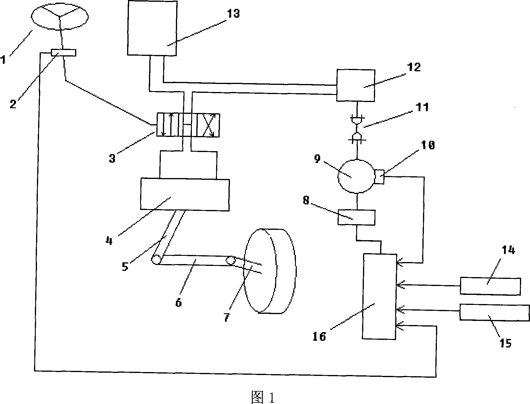
[0024] As shown in Figure 1, the steering wheel 1 is connected to the rotary valve 3, the steering wheel 1 and the rotary valve 3 are connected to the rotation angle sensor 2, and the power steering cylinder 4 of the circulating ball type power steering is connected to the rotary valve 3 and the vertical arm 5 of the steering gear respectively. The other end of the arm 5 is connected to the steering knuckle arm 7 through the steering straight rod 6, and the liquid storage tank 13 is respectively connected to the steering oil pump 12 and the rotary valve 3. The electric motor 9 and the steering oil pump 12 are split-type connection structures and are connected by a universal transmission 11; the angle sensor 2 connected to the steering wheel 1, the drive circuit 8 connected to the motor 9, the current sensor 10, the engine speed sensor 14, and the vehicle running The speed sensors 15 are respectively connected to the controller 16 .

[0025] The specific implementation of the h...


PUM


Abstract

The present invention provides a motor-driving coach hydraulic steering system and method of controlling steering, a motor and a steering pump are split connection structure and connected by an universal driving device; a corner sensor, a driving circuit and a current sensor,a engine revolution transmitter and a vehicle running speed sensor are connected to a controller; firstly reading vehicle running speed signal, steering wheel revolution speed signal, engine speed signal and motor current signal by the controller, dividing the vehicle running condition into six according to judging and analyzing, judging vehicle running condition by calculating obtaining rate; finally, controlling the different speed sections according to the different steering condition, the invention enhances flexibility of system installation arrangement, controls flow of the steering system hydraulic oil that is motor speed by utilizing a multiple conditions control method, a portability and a handle or power responsing quick and stability, eliminates the energy consumption as possible meanwhile meeting the steering performace requirement.

Description

technical field [0001] The patent of the present invention relates to a power steering system of a commercial vehicle, in particular to a hydraulic steering system of a motor-driven bus and a method for controlling the hydraulic steering system. Background technique [0002] The power steering system currently used in buses is mainly a hydraulic power steering system. The power to drive the oil pump comes from the engine, and its power is mainly controlled by a rotary valve or a slide valve. This hydraulic power steering system mainly has the following problems: [0003] (1) For a given hydraulic power steering system, due to the use of engine power to drive, the output hydraulic oil flow of the oil pump cannot be adjusted and controlled. If the designed oil flow is large, it can meet the portability requirements at low speeds, but this will cause The hand feeling becomes worse at high speed, and vice versa when the oil flow rate is small, which makes it difficult to coordi...

Claims


Application Information

Patent Timeline
Patent Type & Authority Applications(China)
IPC IPC(8): B62D5/10B62D5/04B62D5/065B62D6/02B62D6/00B62D113/00B62D127/00
Inventor 何仁周宇
Owner JIANGSU UNIV
Learn More