Ultra-wide band short circuit doublet antenna
A dipole antenna and ultra-wideband technology, which is applied in the field of ultra-wideband short-circuit dipole antennas, can solve the problems of increasing antenna production costs and complex structures
- Summary
- Abstract
- Description
- Claims
- Application Information
AI Technical Summary
Problems solved by technology
Method used
Image
Examples
no. 1 example
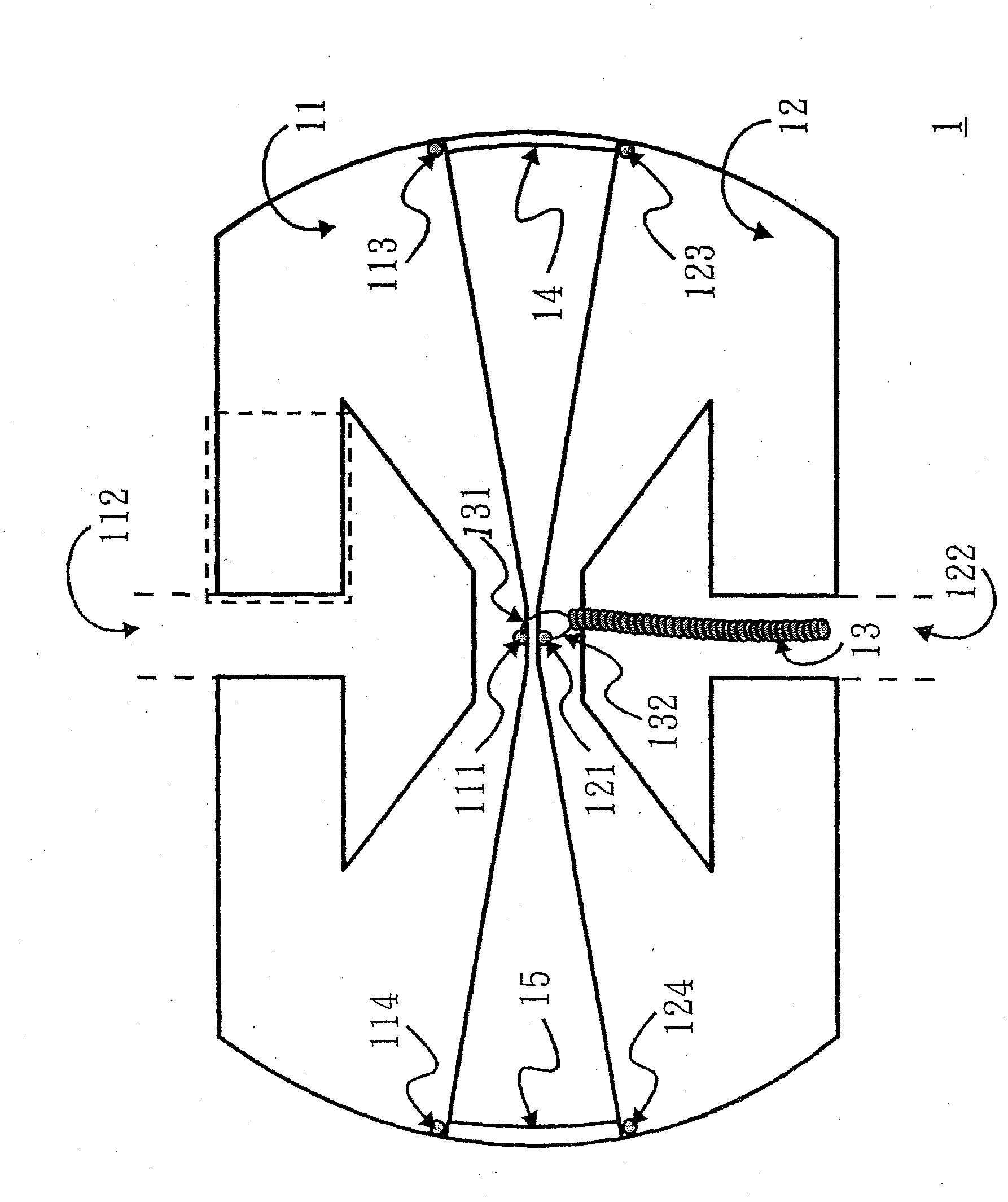
[0030] Please refer to figure 1 , which is a structural diagram of the ultra-broadband short-circuit dipole antenna according to the first embodiment of the present invention. The ultra-broadband short-circuit dipole antenna 1 includes: a coaxial transmission line 13 and two first and second open annular radiating metal sheets 11 and 12 with approximately the same shape. The coaxial transmission line 13 has a central conductor 131 and an outer ground conductor 132 . The first and second opening ring-shaped radiation metal sheets 11 and 12 have signal feed-in points 111 and 121 and openings 112 and 122 respectively, and are approximately symmetrically arranged on both sides of the ultra-wideband short-circuit dipole antenna 1 to form an ultra-wideband short-circuit dipole. The two arms of pole antenna 1.
[0031] like figure 1As shown, the symmetrical arrangement of the first and second open annular radiating metal sheets 11 and 12 makes the two openings 112 and 122 in oppos...
no. 2 example
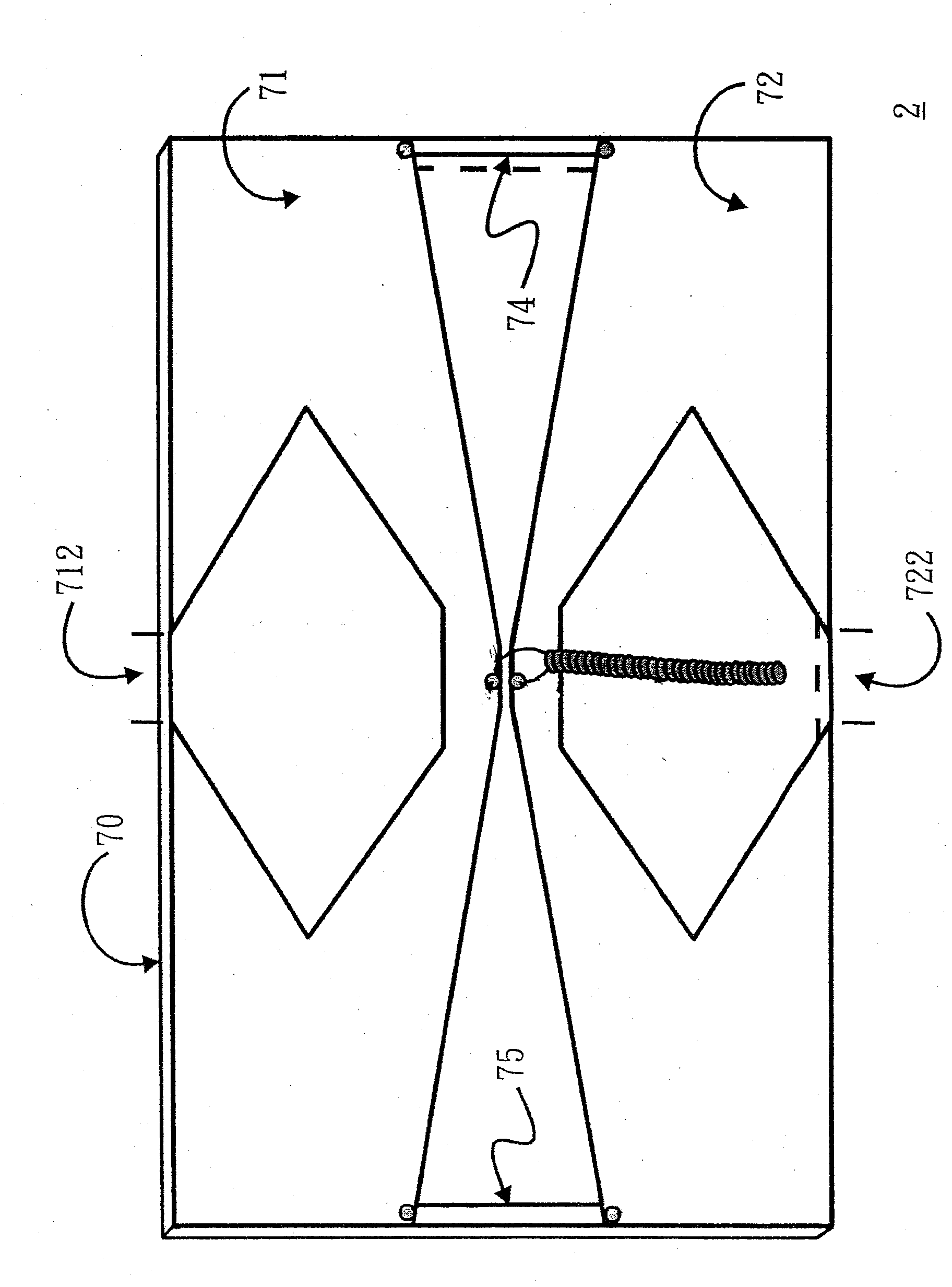
[0040] Please refer to Figure 7 , which shows the structure diagram of the ultra-broadband short-circuit dipole antenna according to the second embodiment of the present invention. The difference from the first embodiment is that the ultra-broadband short-circuit dipole antenna 2 of the second embodiment is formed on the dielectric substrate 70 by etching or printing the first and second open annular radiation metal sheets 71 and 72; , and depending on manufacturing considerations or practical applications, adjust the shapes of the two ring-shaped radiating metal sheets 71 and 72 (the antenna is a rectangle as a whole, which is different from the radian design on both sides of the first embodiment) and the inner edge shapes of the openings 712 and 722. Through the design of the openings 712 and 722 and the short-circuiting thin metal sheets 74 and 75, the resonant current path of the antenna can also be extended to achieve the purpose of reducing the size of the antenna, and ...
no. 3 example
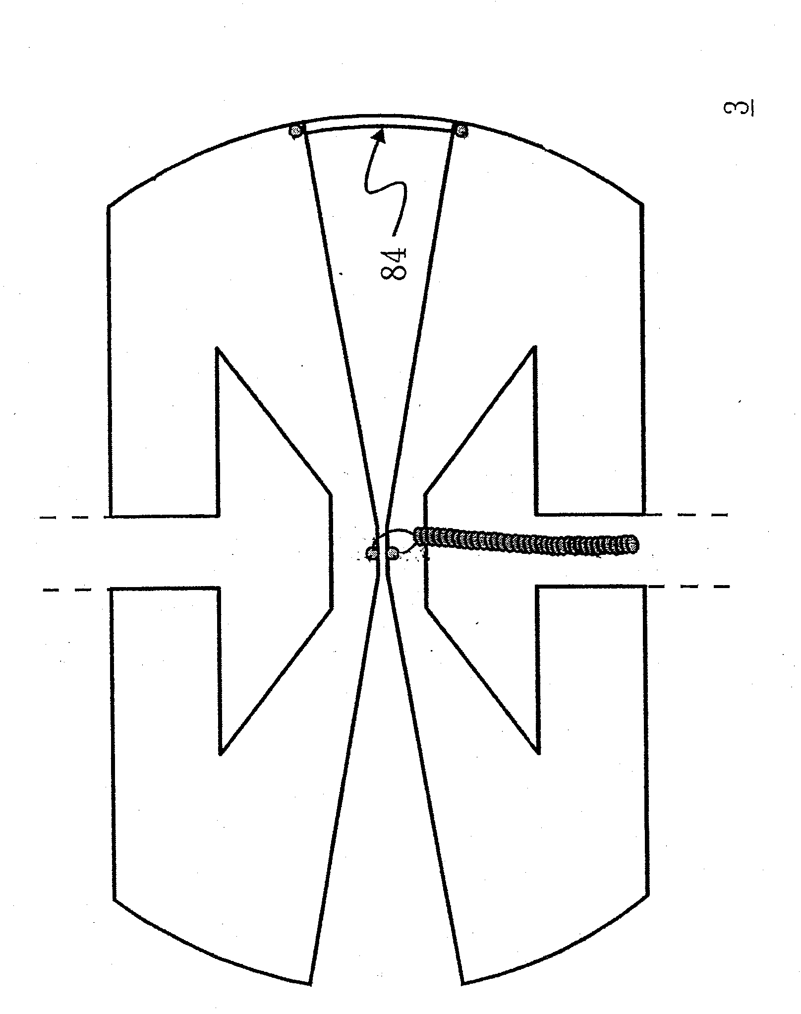
[0042] Please refer to Figure 8 , which is a structural diagram of an ultra-broadband short-circuit dipole antenna according to a third embodiment of the present invention. Compared to figure 1 The ultra-broadband short-circuit dipole antenna 3 only uses a single short-circuit thin metal sheet 84 to adjust the impedance matching of the antenna, and the other structures are the same as those of the first embodiment. Therefore, the ultra-broadband short-circuit dipole antenna 3 can also have the same impedance bandwidth and radiation characteristics as the first embodiment.
[0043] Please refer to Figure 9 , which shows the return loss measurement diagram of the ultra-broadband short-circuit dipole antenna 3 of the third embodiment. exist Figure 9 In , the vertical axis represents the antenna return loss value, and the horizontal axis represents the antenna operating frequency. It can be observed from the measurement results of the return loss that the return loss of th...
PUM
 Abstract
Description
Claims
Application Information
 - R&D
- Intellectual Property
- Life Sciences
- Materials
- Tech Scout
- Unparalleled Data Quality
- Higher Quality Content
- 60% Fewer Hallucinations
Browse by: Latest US Patents, China's latest patents, Technical Efficacy Thesaurus, Application Domain, Technology Topic, Popular Technical Reports.
© 2025 PatSnap. All rights reserved.Legal|Privacy policy|Modern Slavery Act Transparency Statement|Sitemap|About US| Contact US: help@patsnap.com


