
Deep borehole drawing-boring machine tool

A deep hole and machine tool technology, applied in the parts of boring machine/drilling machine, boring/drilling, drilling/drilling equipment, etc., can solve the problems of low machining accuracy, low rigidity of boring bar, rough surface, etc. The effect of bending deformation resistance, ensuring machining accuracy and efficiency

Inactive Publication Date: 2008-09-03
LANZHOU UNIVERSITY OF TECHNOLOGY
View PDF0 Cites 9 Cited by
  • Summary
  • Abstract
  • Description
  • Claims
  • Application Information

AI Technical Summary

Problems solved by technology

However, when the length-to-diameter ratio of the boring bar is greater than 30, due to the low rigidity of the boring bar, the compression deformation during the push-boring process is serious, and vibration occurs, resulting in low machining accuracy, uneven wall thickness, rough surface, and short tool life. Problems that seriously affect machining accuracy and production efficiency
Currently, the deep hole boring machine generally adopts the processing method of fixed boring bar and rotating workpiece, which is suitable for deep hole processing of large diameter pipe fittings, but for slender pipe fittings, it is difficult to overcome the problems of rotational deformation and chatter caused by workpiece rotation

Method used


Image

  • Deep borehole drawing-boring machine tool
  • Deep borehole drawing-boring machine tool
  • Deep borehole drawing-boring machine tool

Examples


Embodiment Construction

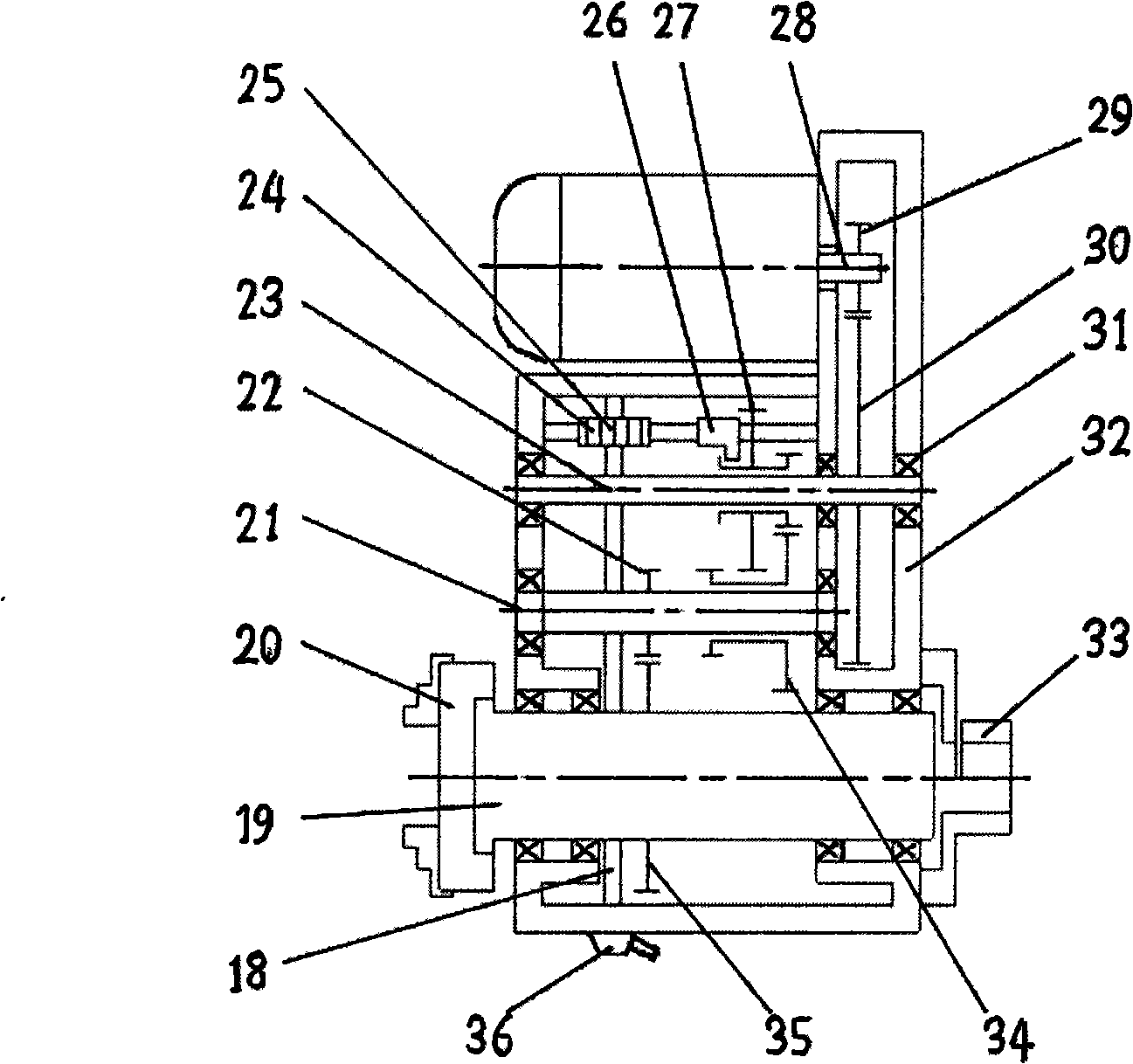
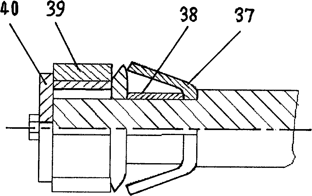
[0007] Such as figure 1 As shown, the present invention is a drawing and boring machine tool for processing deep holes of slender tubes. It includes a body 11, a headstock 2, a centering bracket 6, an oil applicator 8, a front support 7, and a rear oil applicator. Support 9, boring tool front support 1, boring bar 12, boring bar support frame 10, rotary joint 16, pallet 14, boring bar drive box 15, feed screw 13 and tool feed drive box 17, headstock 2 is installed in On the left end of the fuselage 11, the boring tool front support 1 is fixed in the spindle box along the main axis AA′. The centering bracket 6 is fixed on the fuselage 11, and the oil applicator 8 is fixed at the end of the workpiece in the middle of the fuselage 11 for boring tools. 3 for cooling and lubrication, the front support 7 of the oil applicator and the rear support 9 of the oil applicator are fixedly connected to the front side of the oil applicator 8 along the main axis AA′ direction, and the boring bar...


PUM


Abstract

A draw-boring machine tool for processing deep hole of slim pipe aims to meet different processing requirement for pipes of different types. The draw-boring machine tool comprises a spindle box arranged on the left end of a frame; a front boring tool support fixed in the spindle box along a main axis direction; a centering support fixed on the frame; an oil dispenser fixed on the tail end of a middle part on the frame; a front and a rear oil dispenser supports fixedly connected in front of the oil dispenser along the main axis direction; a boring bar sequentially penetrating through the front oil disperser support, the rear oil dispenser support, a boring bar support frame and a boring bar drive box from left to right along the main axis direction and fixedly connected with a three-jaw chuck; a rotary joint arranged on the left end face of the boring rod; the boring bar drive box fixedly connected with a splint; and a feed drive box fixedly connected with the right side of the frame and connected with a feed screw, wherein the feed screw drives the splint and the boring bar drive box arranged thereon to make reciprocate, thereby driving the boring bar to make longitudinal movement; and the front end of the boring rod is fixedly connected with an elastic boring tool support.

Description

Technical field [0001] The invention relates to a machine tool for boring and broaching. Background technique [0002] The deep hole boring machines used for inner hole processing of pipe parts at home and abroad mainly adopt the slender boring bar push type boring processing method. When the length-to-diameter ratio of the boring bar is less than 30, the rigidity of the boring bar is high, and the vibration is small. At the same time, the lubricating fluid can be passed through the inner hole of the boring bar to fully cool and lubricate the cutting edge, and use high-pressure liquid to wash away the iron chips on the tool head. , To ensure the processing accuracy and stability. However, when the length-to-diameter ratio of the boring bar is greater than 30, due to the low rigidity of the boring bar, the compression and deflection during the push boring process will be severe and chattering will occur, resulting in low machining accuracy, uneven wall thickness, rough surface, an...

Claims


Application Information

Patent Timeline
Patent Type & Authority Applications(China)
IPC IPC(8): B23B41/02B23B47/14B23B29/14
Inventor 龚俊辛舟侯运丰刘永平李文辉宁会峰
Owner LANZHOU UNIVERSITY OF TECHNOLOGY
Learn More