Manufacturing method of glasses elastic hinge case

A technology of elastic hinges and manufacturing methods, which is applied in the direction of manufacturing tools, glasses/goggles, and other manufacturing equipment/tools, and can solve the problems of increased cutting difficulty, complicated manufacturing process, and limited bar width, so as to facilitate subsequent processing, Good production continuity, eliminating the effect of bending and not straight

Inactive Publication Date: 2008-09-03
浙江康华眼镜有限公司
View PDF0 Cites 5 Cited by
  • Summary
  • Abstract
  • Description
  • Claims
  • Application Information

AI Technical Summary

Problems solved by technology

[0003] 1. When each bar is cut, some bars will be left in the fixture as scraps and cannot be used, and they will be treated as waste. For example, if the length of the shell blank is 5mm and the length of the remaining scraps is 20cm, the scraps can also be made 40 shell blanks; the bar is a straight bar, the length of which is generally not more than 3m due to manufacturing conditions, and 6.6% of the bar can only be wasted if the length of the leftover head is 20cm;
[0004] 2. The forming process of the shell blank is completed on multiple single-process equipment, and each process must be re-clamped once. Multiple clamping affects the positioning accuracy of the workpiece and reduces the processing quality. It will also cause bruises and clamps on the product surface. For defects such as marks and burrs, auxiliary processes must be added to eliminate these surface defects. The process is complex and the manufacturing cost is high; it is difficult to form automated continuous production with multiple single-process equipment independent processing, and the shell blanks are constantly turned over between various process equipment, which is time-consuming and laborious , low work efficiency and high production cost;
[0005] 3. The side of the shell blank is the cut surface of the bar, and the side is an important part of the final product shell. The quality of the surface directly affects the product quality. In order to make the surface roughness meet the design requirements, only by improving the cutting accuracy or increasing the Subsequent processing is used to alleviate the defects of excessive surface roughness caused by cutting, which will increase the difficulty of cutting, increase the processing cost, and make the manufacturing process more complicated;
[0006] 4. The top surface of the bar is used as the top surface of the final molded elastic hinge shell, and generally no further processing is required. The requirements for molds and equipment are high during bar manufacturing, and the manufacturing cost is increased; the width of the bar is limited, and the shape of the top surface is pre-formed. Correspondingly, the length and shape of the top surface of the shell blanks to be intercepted are limited, and the elastic hinge shells produced have single specifications and poor versatility of raw materials. In order to manufacture hinge shells of different shapes, only special-shaped bars with different thicknesses and large differences in aspect ratio can be used as production material

Method used


Image

  • Manufacturing method of glasses elastic hinge case
  • Manufacturing method of glasses elastic hinge case
  • Manufacturing method of glasses elastic hinge case

Examples


Embodiment 1

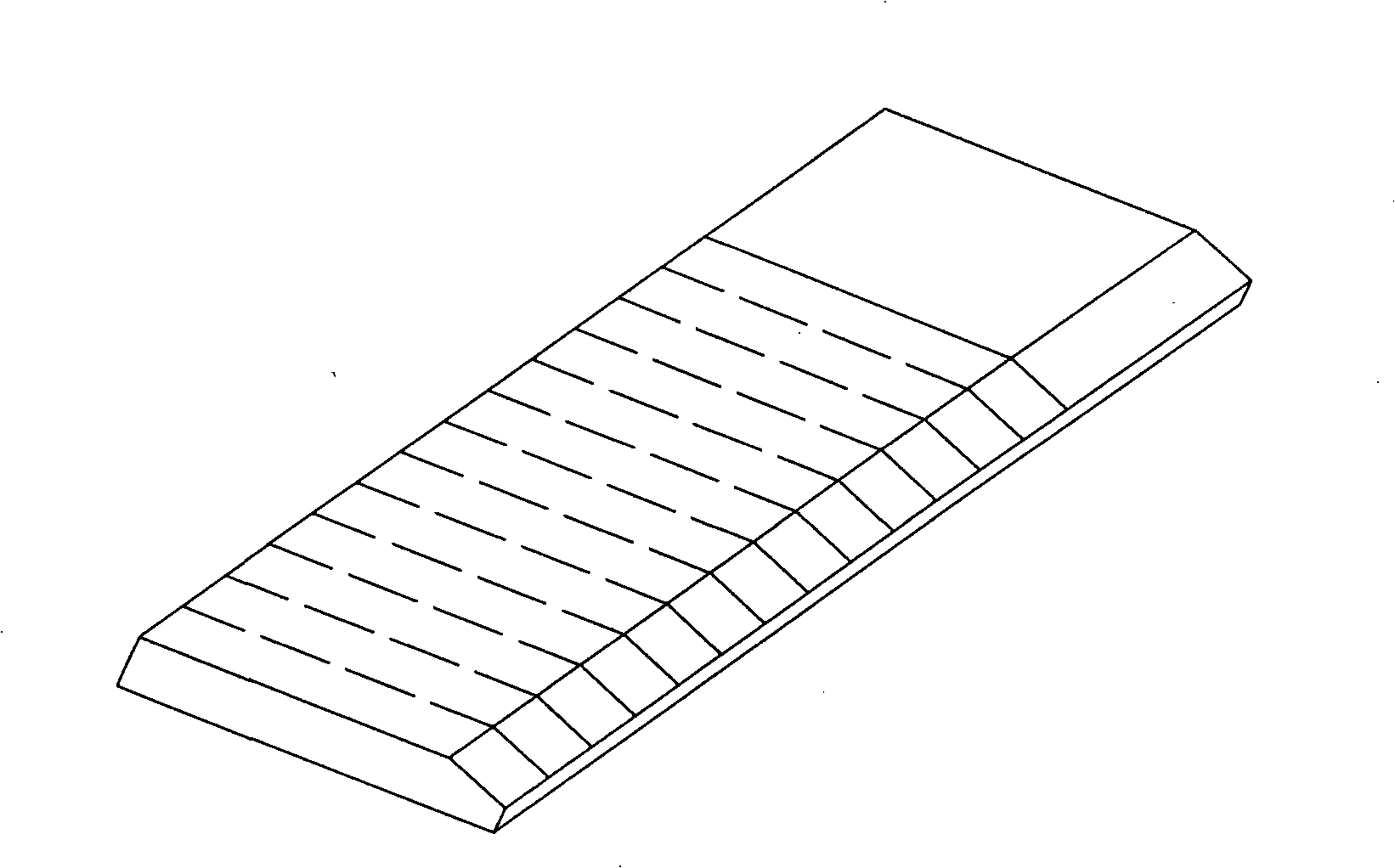
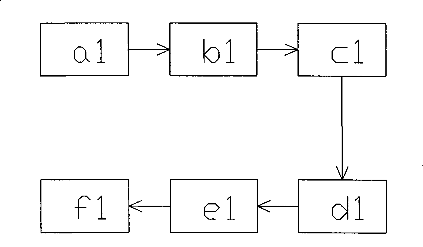
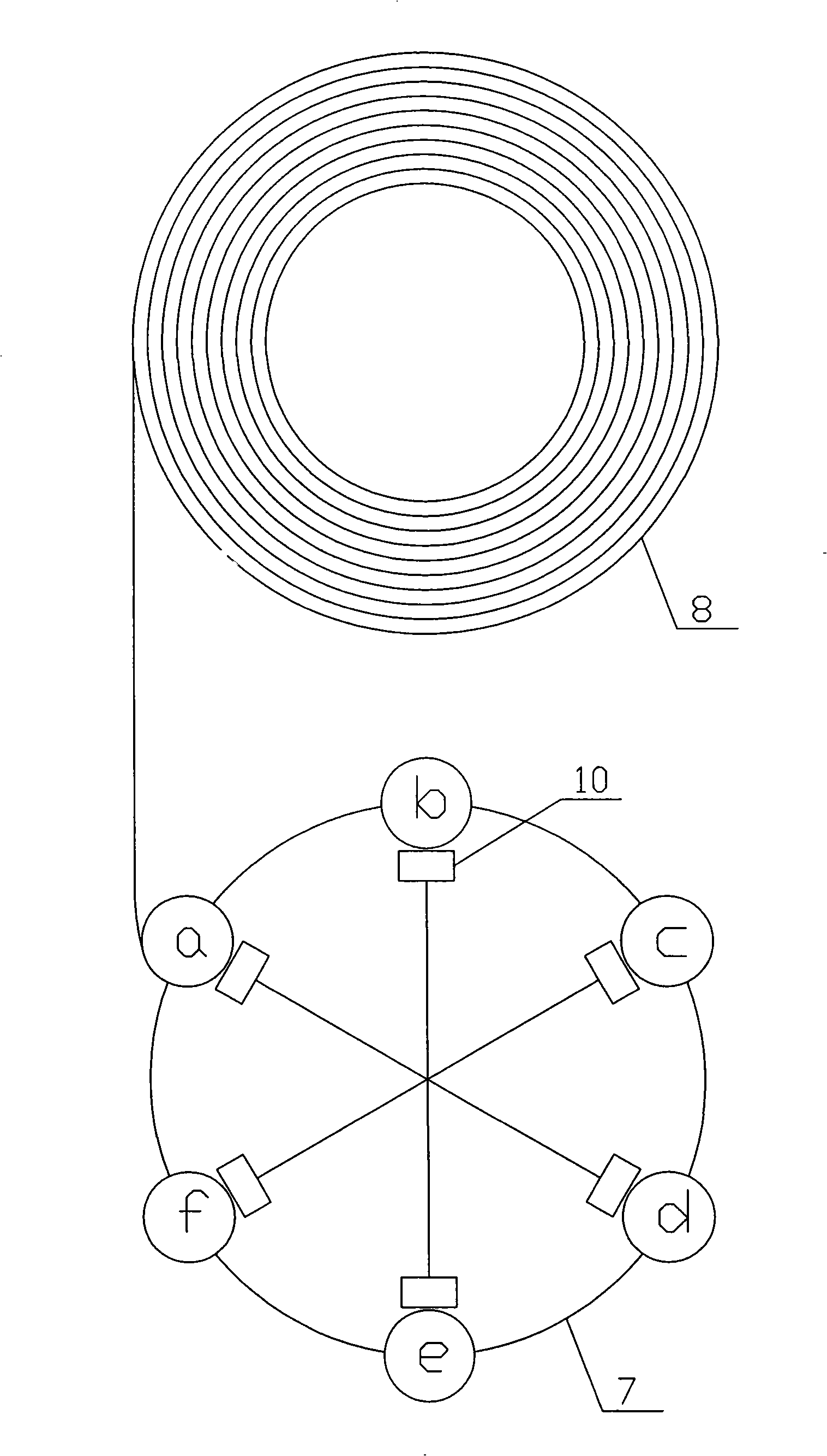
[0029] Example 1 as image 3 ~ As shown in Figure 7, a method for manufacturing the elastic hinge shell of glasses, including six stations arranged in sequence: a. cutting station, b. top milling station, c. punching station, d. Tail milling station, e. boring station, f. punching station, the six stations are distributed around the periphery of the rotary table type combined machine tool 7, and the middle of the rotary table type combined machine tool is provided with the same number of stations Six fixtures 10; the six fixtures are uniformly distributed and coaxially arranged in the circumferential direction, and can rotate synchronously. During work, the shell blanks are clamped one by one, and the shell blanks are stepped and sent to the circle around the periphery of the turntable combined machine tool according to the rotation direction of the turntable combined machine tool. At multiple stations, each functional part of the shell blank is processed when the fixture stop...

Embodiment 2

[0036] Example 2 as Figure 8 ~ Figure 1 As shown in 2, compared with embodiment 1, a milling station g and corresponding fixtures are added to the rotary table type combined machine tool 7 used in embodiment 2, and the milling station is located at the boring station e and the punching station Between stations f; seven fixtures are uniformly distributed and coaxially arranged in the circumferential direction, and can rotate synchronously. During work, the shell blanks are clamped one by one, and the shell blanks are sent to the surrounding rotary table type machine tool 7 in steps according to the rotation direction of the rotary table type combined machine tool. At multiple stations on the periphery, each functional part of the shell blank is processed when the fixture stops at the corresponding station, so that the cycle is repeated to achieve continuous production; the two sides and the bottom of the shell blank do not need to be processed, and the two sides are fixtures c...


PUM


Abstract

The invention belongs to the field of glasses accessory manufacture technology, in particular to the manufacture method of elastic hinge housing of glasses, which has simple process, good material generality and higher material utilization rate to overcome the disadvantages of prior art, such as complicated manufacture method, poor material generality and low material utilization rate. The manufacture method comprises the following steps: changing the raw material for manufacturing elastic hinge housing of glasses rod material into metal wire material; cutting the selected wire material segment by segment to obtain a plurality of housing blanks corresponding to the length of the hinge housing; clamping the housing blanks by a plurality of fixtures on a rotary disc combined machine tool one by one; and feeding the housing blanks to each work position stepwise to achieve processing. Compared with prior art, the method has the advantages of high quality of the elastic hinge housing, good generality and high utilization rate of the metal wire, continuous and automatic production and greatly improved production efficiency.

Description

【Technical field】 [0001] The invention belongs to the technical field of glasses accessory manufacturing, in particular to a method for manufacturing an elastic hinge shell of glasses. 【Background technique】 [0002] The elastic hinge is an important part used to connect the frame and the mirror legs on the spectacle frame, and includes a shell and an elastic body contained in the shell. The function of the elastic hinge is to control the elastic opening and closing of the two temples, so that the distance between the two temples can adapt to the shape of the wearer's face, so as to achieve the purpose of comfortable wearing. The manufacturing method of existing glasses elastic hinge shell is as figure 1 with figure 2 As shown: the raw material is a bar, and the cross-sectional shape of the bar along the width direction is the same as that of the hinge shell in the length direction. The bar is clamped by the feeding clamp on the blanking station a1, and the bar is continu...

Claims


Application Information

Patent Timeline
IPC IPC(8): B23P15/00B23P23/00G02C5/22
Inventor 高克胡林友
Owner 浙江康华眼镜有限公司
Why Eureka
Try Eureka