Great dynamic range hartmann wavefront sensor and its test method

A technology with a large dynamic range and a sensor, which is applied in the use of optical devices to transmit sensing components, instruments, measuring devices, etc., can solve problems such as unreliable wavefront information, and achieve the effect of improving the dynamic range of measurement

Inactive Publication Date: 2008-09-10
SHANGHAI INST OF OPTICS & FINE MECHANICS CHINESE ACAD OF SCI
View PDF0 Cites 22 Cited by
  • Summary
  • Abstract
  • Description
  • Claims
  • Application Information

AI Technical Summary

Problems solved by technology

But when the spot sequence is misplaced, that is image 3 In the cases shown in sub-areas 6-4 and 6-5, the algorithm will

Method used


Image

  • Great dynamic range hartmann wavefront sensor and its test method
  • Great dynamic range hartmann wavefront sensor and its test method
  • Great dynamic range hartmann wavefront sensor and its test method

Examples


Embodiment Construction

[0029] The present invention will be further described below in conjunction with the embodiments and accompanying drawings, but the protection scope of the present invention should not be limited thereby.

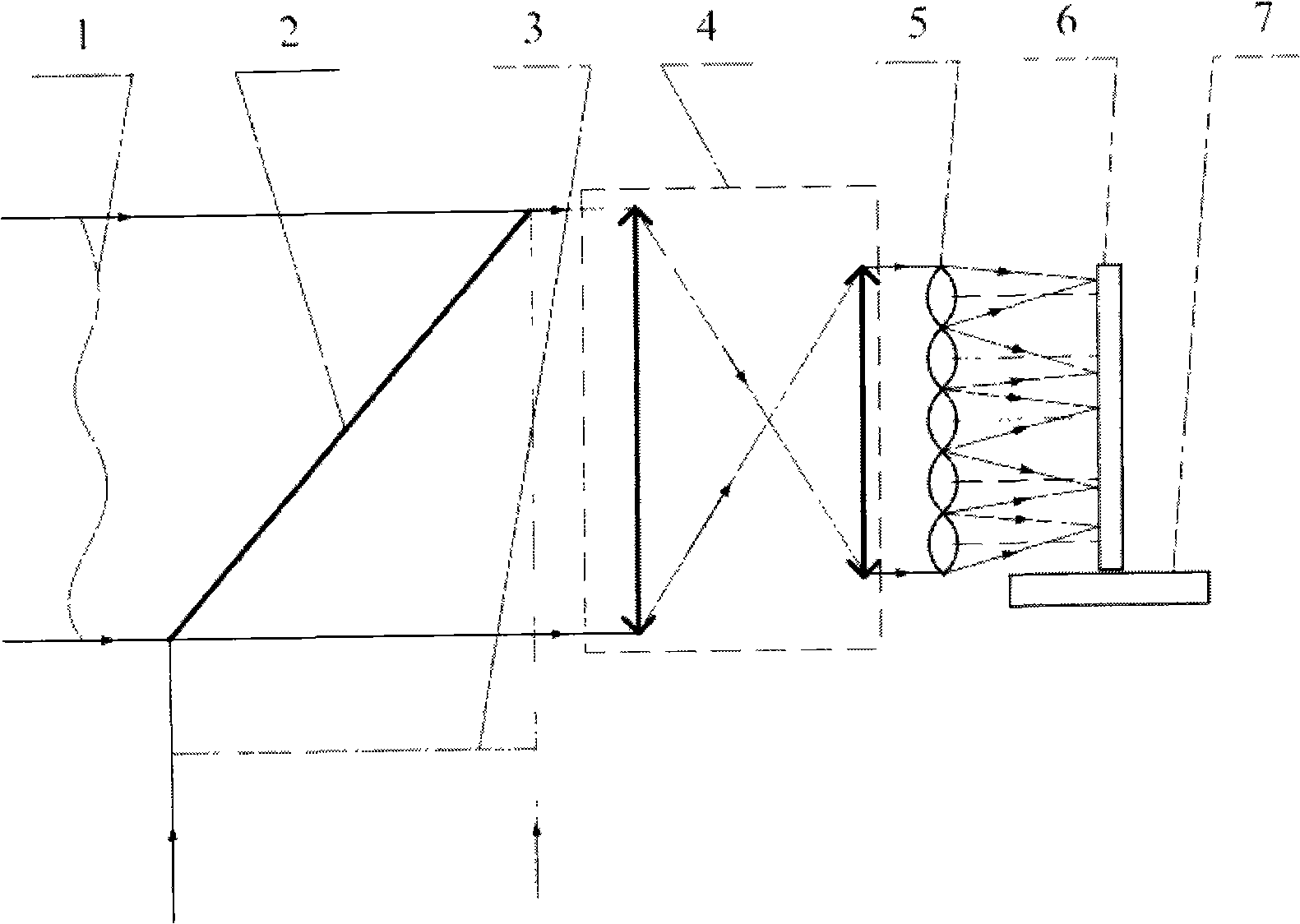
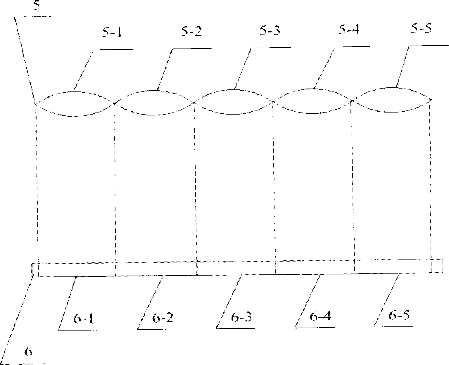
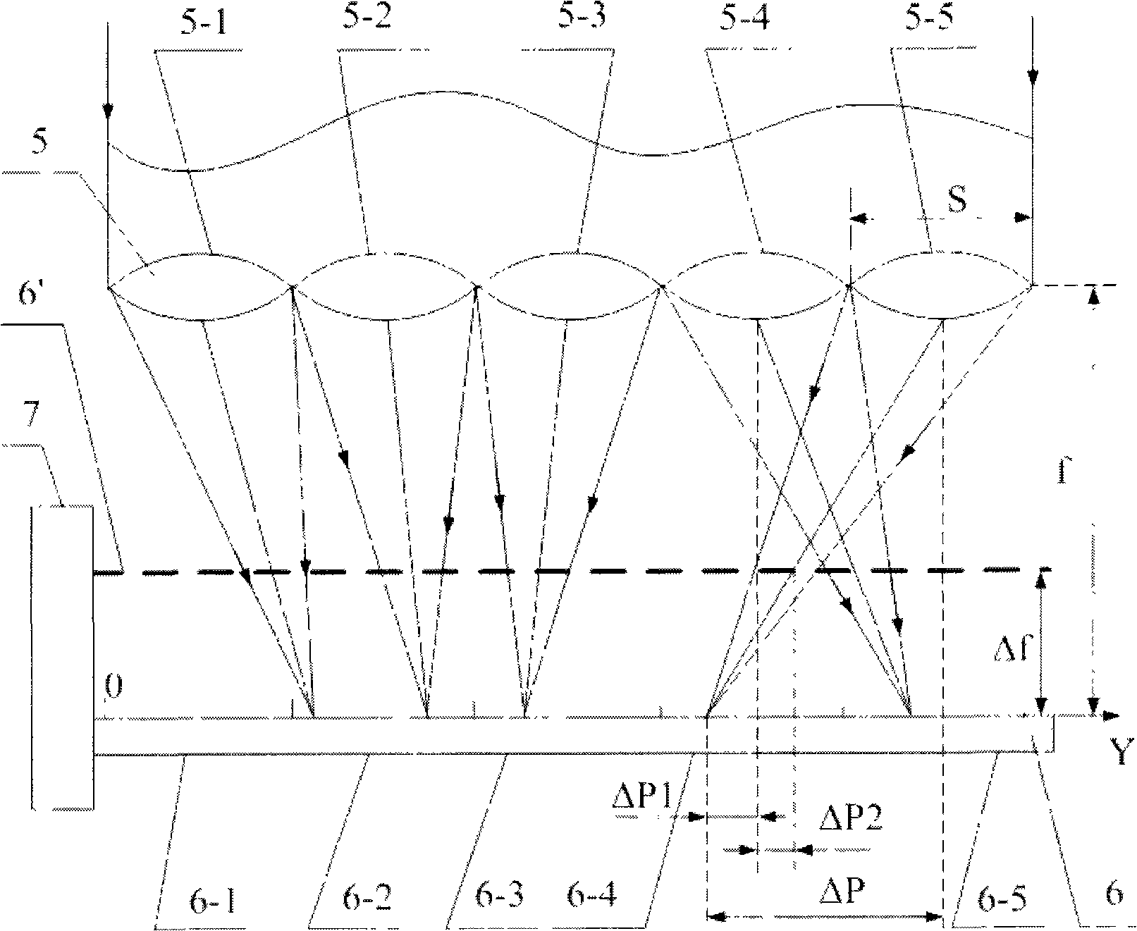
[0030] see first figure 1 , figure 1 It is a structural schematic diagram of an embodiment of the present invention. As can be seen from the figure, the Hartmann wavefront sensor with a large dynamic range of the present invention includes a plane wave reference source 3, a beam splitter 2, an optical matching system 4, a wavefront division array 5, and a photodetector Array 6 and the Hartmann wavefront sensor that the computer that has data processing software is formed, is characterized in that there is also a translation platform 7, and described photodetector array 6 is fixed on this translation platform 7, drives this translation platform 7 to move, Drive the light intensity detector array 6 to move along the normal direction of its photosensitive surface.

[0031]...


PUM


Abstract

The invention provides an HWS (Hartmann wavefront sensor) of large dynamic range and a testing method thereof. The structure of the Hartmann wavefront sensor comprises the Hartmann wavefront sensor consisting of a plane wave reference source, a spectroscope, an optical matching system, a wave surface cutting array, a photoelectric detector array and a computer. The Hartmann wavefront sensor is characterized in that a translation platform is also arranged; the photoelectric detector array is fixed on the translation platform. When an aberrated wavefront exceeds the natural dynamic range of the Hartmann wavefront sensor, the movement of the photoelectric detector is controlled by the translation platform; furthermore, the coordinates of mass center of each facula under the initial state and off-focus state of photoactive surface are respectively measured by the photoelectric detector array. According to the off-focus quantity, the period and focal distance of the wave surface cutting array and the displacement quantity of each facula mass center under the off-focus state, the practically owned aperture area of the facula is worked out by a facula belonging sub-aperture recognition algorithm, thus realizing the correct recognition of the facula which exceeds the dynamic range. The Hartmann wavefront sensor of large dynamic range and the testing method thereof effectively improves the measured dynamic range of the traditional Hartmann wavefront sensor.

Description

technical field [0001] The invention relates to an optical wavefront sensor, in particular to a Hartmann wavefront sensor with a large dynamic range and a testing method thereof. Background technique [0002] The Hartmann wavefront sensor usually consists of a wavefront segmentation array (usually a microlens array), a photodetector array (usually a CCD detector), a computer, and data processing software. The sub-lenses in the microlens array divide the incident wavefront into corresponding sub-aperture areas, and focus the light beams within the sub-aperture range onto the photosensitive surface of the CCD detector. The image information of the spot array is collected by the CCD detector controlled by the image acquisition signal, and then the collected image information is transmitted to the computer, and the data processing software of the computer calculates the difference between the centroid coordinates of the distortion wavefront spot and the reference wavefront centr...

Claims


Application Information

Patent Timeline
IPC IPC(8): G01J9/00G01D5/26
Inventor 姜有恩李学春
Owner SHANGHAI INST OF OPTICS & FINE MECHANICS CHINESE ACAD OF SCI
Why Eureka
Try Eureka