
Sequence image correction based pneumatic optical transmission effect evaluation method and apparatus

A technology of aero-optics and transmission effects, applied in the field of interdisciplinary science, can solve the problems of low efficiency of multi-machine parallelism, complex and large systems, and low integration, so as to shorten the time of simulation function, overcome the limited computing performance, and expand strong effect

Inactive Publication Date: 2008-09-10
HUAZHONG UNIV OF SCI & TECH
View PDF0 Cites 30 Cited by
  • Summary
  • Abstract
  • Description
  • Claims
  • Application Information

AI Technical Summary

Problems solved by technology

The advantage is that the computing performance is improved, and the disadvantage is that the system is complex and huge, and the integration level is not high. Due to the bottleneck of Ethernet data communication bandwidth, the efficiency of multi-machine parallelism is not high, and it cannot receive external camera data directly input, and cannot perform real-time correction evaluation.
[0022] The above calculation method is suitable for offline restoration and correction of high-speed flow field degradation images. It is inconvenient to carry, cannot realize real-time correction, and is inconvenient to carry to the experimental site

Method used


Image

  • Sequence image correction based pneumatic optical transmission effect evaluation method and apparatus
  • Sequence image correction based pneumatic optical transmission effect evaluation method and apparatus
  • Sequence image correction based pneumatic optical transmission effect evaluation method and apparatus

Examples


Embodiment Construction

[0060] The present invention will be further described in detail below with reference to the drawings and examples.

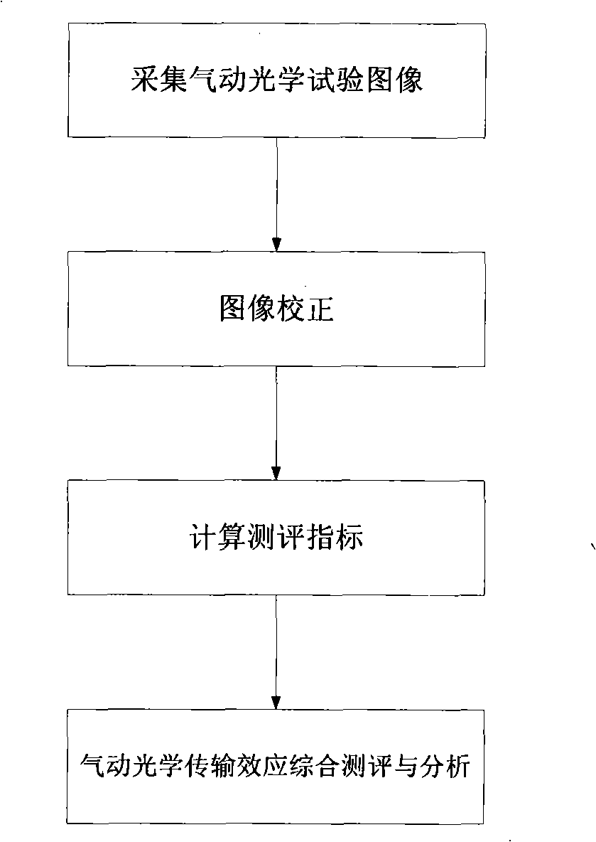
[0061] Such as figure 1 As shown, the evaluation method of the present invention includes the following steps:

[0062] (1) Collect aero-optical test images g(x, y), (x, y) respectively represent the pixel coordinates in the height and width directions of the image;

[0063] The collected images can be serial image data of aero-optical effects obtained in wind tunnel tests, or image data of aero-optical transmission effects obtained by using high-speed aircraft with imaging detectors during high-speed flight.

[0064] (2) Correct the collected aero-optical test image g(x, y);

[0065] For the collected aero-optical test image g(x, y), an image correction algorithm is used to estimate the unknown reference image f(x, y) and the point spread function h(x, y). The estimated corrected image and point spread function are used respectively with Said.

[0066] The pres...


PUM


Abstract

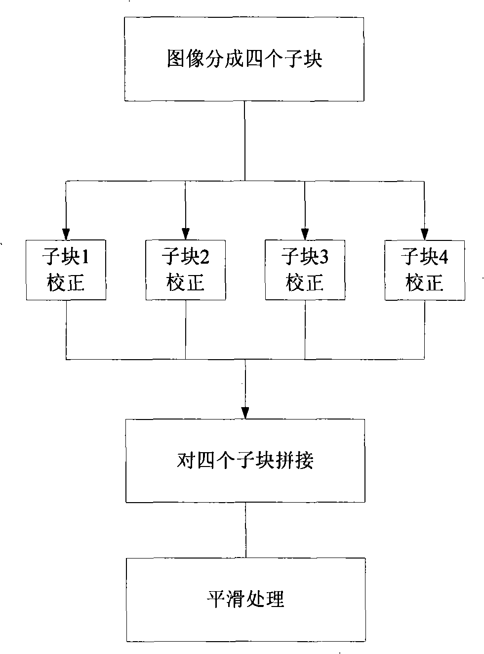
The invention discloses a pneumatic optical transmission effect evaluation method and a device which are based on sequence image correction. The pneumatic optical transmission effect evaluation method calculates a correction image and a point spread function by three correction methods of space blocking concurrent correction, two-dimensional sampling concurrent correction and concurrent iterative correction, and gains the evaluation indexes by further calculation; the evaluation indexes are used for measuring, analysing and evaluating the pneumatic optical transmission effect. Aiming at the pneumatic optical transmission effect evaluation method, a calculation processing device based on a host computer, a multifunctional image collecting control card and a concurrent digital signal assist processing card is designed. The collecting, processing, memorizing and displaying of different passage image source data can be achieved by the calculation processing device; by virtue of the characteristics of high parallelism of the evaluation device calculation and the extensibility of the processing unit, the quantity of the calculation processing units is smartly adopted so as to achieve the real-time processing; the evaluation device of the invention has the advantages of small volume, light weight, and easy carry.

Description

Technical field [0001] The invention belongs to the field of cross-science technology combining aero-optics, image processing and measurement technology, and specifically relates to a method and device for evaluating aero-optical transmission effect based on sequential image correction. Background technique [0002] Aero-optics is a subject that studies the influence of high-speed detours on high-speed aircraft imaging and detection and its correction. When a high-speed aircraft with an optical imaging detection system flies in the atmosphere, a complex flow field is formed between the optical hood and the incoming flow, which causes thermal radiation and light transmission interference to the optical imaging detection system, causing image shift, jitter, and Blur, this effect is called aero-optical effect. When the optical imaging detection system carried by the high-speed aircraft flies in the atmosphere, the violent interaction between the optical hood and the incoming flow wi...

Claims


Application Information

Patent Timeline
IPC IPC(8): G01M9/00G01M9/02
Inventor 张天序洪汉玉钟胜颜露新刘纯胜付长江符俊杰张泽彬陈荣华王进汪小平
Owner HUAZHONG UNIV OF SCI & TECH
Learn More