Method for analyzing liquid metal and device for use in this method

A liquid metal and equipment technology, applied in the field of analyzing the composition of liquid metal molten pool, can solve the problems of prolonging the measurement time, impossible to correctly measure the current composition of molten pool, and further analysis, so as to reduce chemical erosion and prolong service life Effect

A liquid metal and equipment technology, applied in the field of analyzing the composition of liquid metal molten pool, can solve the problems of prolonging the measurement time, impossible to correctly measure the current composition of molten pool, and further analysis, so as to reduce chemical erosion and prolong service life Effect

CN101263380AInactive Publication Date: 2008-09-10ALERIS SWITZERLAND

Image

  • Method for analyzing liquid metal and device for use in this method
  • Method for analyzing liquid metal and device for use in this method

Examples


Embodiment Construction

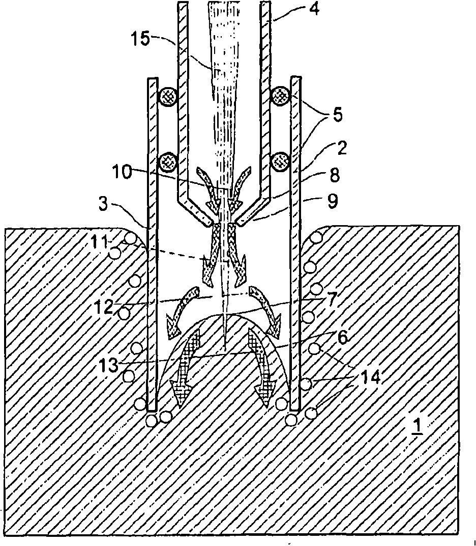
[0038] exist figure 1 In , 1 represents a part of the molten metal pool, such as the molten aluminum alloy pool. The immersion pipe system shown in this example with a jacket 3 extends into the bath. The air supply pipe 4 is concentric with the casing inside the casing. The bushing 3 and the gas supply pipe 4 are connected to each other by an O-ring 5 which also provides a seal against gas leakage.

[0039] As a result of the submersion of a part of the casing 3 into the molten pool 1, a convex meniscus is formed inside the casing. Preferably at least a portion of the inner wall of the sleeve is made of a non-wetting material. A laser beam 15 generated by a laser source (not shown) meets the meniscus at the location of the meeting surface 7 above the focal point of the laser beam to prevent positioning problems and to prevent the gas above the meniscus from forming a plasma.

[0040] The channel 8 of the air supply pipe 4 has a central narrowing 9 .

[0041] The direction...


PUM


Abstract

Method for analyzing the composition of a bath comprising liquid metal, in which a laser beam is directed onto a surface of the bath and in which at least part of the metal forms a sample which is analyzed, wherein, at least at the location where the laser beam meets the bath, impurities at the surface of the bath are removed by purging with a stream of a purge gas.

Description

technical field [0001] The present invention relates to a method of analyzing the composition of a liquid metal bath and an apparatus for use in the method. Background technique [0002] A method and apparatus of this type is known from British patent application GB2154315A. The published application describes a method and apparatus for analyzing the composition of molten steel. [0003] According to the method described, a probe provided with means for delivering a laser beam is positioned above a molten steel bath. The part of the steel that the laser strikes emits radiation of a specific element. The emitted radiation is transmitted via an optical system (which is also housed in the probe) to a spectrometer for analysis. The composition of the steel can be obtained from the analysis results. This method is also known as LIBS (Laser-Induced Breakdown Spectroscopy). [0004] On the side facing the molten pool, the probe is provided with a ceramic tube which protects th...

Claims


Application Information

Patent Timeline
10 Sep 2008
Publication
CN101263380A
IPC
G01N21/71; G01N21/15; G01N21/69
CPC
G01N2021/695; G01N2021/151; G01N21/718; G01N21/15; G01N21/69
Inventors
P·A·德弗里斯