Double reaction area integral waste gases biodecontamination reactor and waste gas treatment method thereby

A dual-reaction zone, biological purification technology, applied in chemical instruments and methods, separation methods, air quality improvement, etc., can solve problems such as reducing the footprint of the reactor, and achieve compact structure, no secondary pollution, and simple structure. Effect

Inactive Publication Date: 2008-09-17
RES CENT FOR ECO ENVIRONMENTAL SCI THE CHINESE ACAD OF SCI
View PDF0 Cites 14 Cited by
  • Summary
  • Abstract
  • Description
  • Claims
  • Application Information

AI Technical Summary

Problems solved by technology

[0007] The purpose of the present invention is to overcome the defects of the traditional single waste gas biological purification reactor in processing complex waste gas, and provide an

Method used


Image

  • Double reaction area integral waste gases biodecontamination reactor and waste gas treatment method thereby
  • Double reaction area integral waste gases biodecontamination reactor and waste gas treatment method thereby
  • Double reaction area integral waste gases biodecontamination reactor and waste gas treatment method thereby

Examples


Embodiment 1

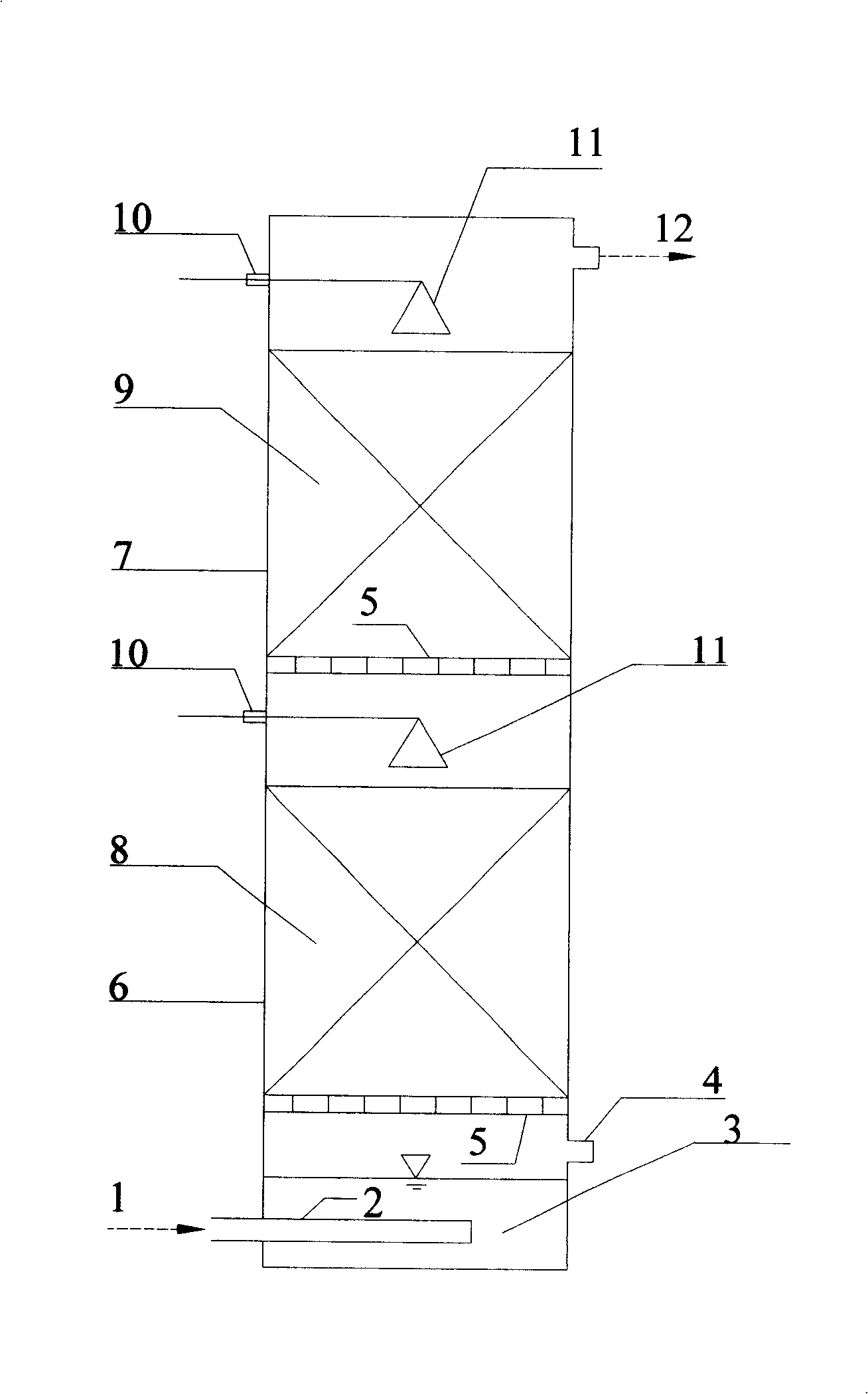
[0037]See figure 1 . The dual-reaction zone integrated exhaust gas biological purification reactor made of plexiglass has a basic structure of a cylinder with a diameter of 90mm and a total volume of 5L. It is divided upwards by two gas distribution plates 5 into gas humidification zones 3, Three parts of the first bioreaction zone 6 and the second bioreaction zone 7;

[0038] An air inlet 1 is opened on the side wall of the lower part of the gas humidification area, a perforated pipe 2 is installed at the air inlet, and a drain port 4 is opened on the side wall of the upper part of the gas humidification area;

[0039] In the first biological reaction zone, acid-resistant inert first biological reaction zone packing 8 is housed, and a spray liquid inlet 10 is arranged on the side wall of the first biological reaction zone, and a connection nozzle 11 is installed at the spray liquid inlet. Pipeline, the nozzle is above the filler in the first biological reaction zone; the r...

Embodiment 2

[0045] The reactor is as in Example 1.

[0046] High-concentration exhaust gas enters the gas humidification zone 3 from the air inlet 1 at the lower part of the gas humidification zone 3 through the gas perforated tube 2. At this time, the liquid level in the humidified zone is higher than the height of the gas perforated tube 2, and the gas goes up after being humidified in the liquid phase Flow, enter the first biological reaction zone 6 through the first gas distribution plate 5, the first biological reaction zone operates at an acidic pH, the nozzle 11 regularly sprays the acidic nutrient solution through the pipeline, most of the waste gas produces acid, hydrophobic Reactive gas pollutants are degraded by acidophilic bacteria and fungi on the porous media packing (such as sponge, polypropylene pellets or ceramics, etc.) in the first biological reaction zone, and the gas load is greatly reduced; undegraded low-concentration pollutants and metabolic intermediates The produ...


PUM


Abstract

The invention relates to an integrated style waste gas bio-purifying reactor with two reaction zones, belonging to the equipment utilizing a bioreactor to process the waste gas. A container is divided into a gas humidifying zone, a first biological reaction zone and a second biological reaction zone from bottom to top in sequence by two gas distribution plates. An air inlet and a perforated pipe are arranged on the sidewall of the lower part of the gas humidifying zone, and a drainage outlet is arranged on the sidewall of the upper part. The first biological reaction zone is filled with acid-resistance inert fillers, and the second biological reaction zone is also filled with inert fillers. A spraying liquid inlet and a pipeline connected with a nozzle are arranged on sidewalls of both the first and the second biological reaction zones. An air outlet is also arranged on the sidewall of the second biological reaction zone. Most pollutants in the waste gas are degraded by acidophil bacteria and epiphyte of fillers in the first biological reaction zone. The non-degraded low-concentrated pollutants and metabolic intermediates are fully degraded by heterotrophic bacteria of fillers in the second biological reaction zone. The purified gas is discharged from the air vent.

Description

technical field [0001] The invention belongs to equipment for treating waste gas by using a bioreactor, in particular to a double reaction zone integrated waste gas biological purification reactor and a waste gas treatment method thereof. Background technique [0002] In the process of industrial and agricultural production, sewage treatment, garbage treatment and composting, some waste gas containing volatile organic or inorganic substances will pollute the surrounding environment and cause serious harm to human health and the ecological environment. At present, the control of air pollution and waste gas has attracted more and more attention. [0003] Biological method is a technology developed in recent decades for waste gas treatment. Compared with conventional physical and chemical purification technologies such as absorption, adsorption, catalysis, and incineration, biological methods have the advantages of good treatment effects, low operating costs, no secondary poll...

Claims


Application Information

Patent Timeline
IPC IPC(8): B01D53/84
CPCY02A50/20
Inventor 刘俊新刘建伟
Owner RES CENT FOR ECO ENVIRONMENTAL SCI THE CHINESE ACAD OF SCI
Why Eureka
Try Eureka