Ultra-high non-linear photon crystal optical fiber based on narrow slit effect

A photonic crystal fiber and fiber technology, applied in nonlinear optics, cladding fiber, optical waveguide light guide, etc., can solve problems such as high nonlinear coefficient, and achieve the effect of reducing the effective mode field area

Inactive Publication Date: 2008-10-08
BEIHANG UNIV
View PDF0 Cites 11 Cited by
  • Summary
  • Abstract
  • Description
  • Claims
  • Application Information

AI Technical Summary

Problems solved by technology

[0007] The technical problem to be solved by the present invention is to symmetrically distribute two high-refractive-index materials with elliptical or square cross-sections at the fiber core, and to further compress the effective area of ​​the mode field through the slits formed by the high-refractive-index materials to obtain superhigh nonlinear coefficient

Method used


Image

  • Ultra-high non-linear photon crystal optical fiber based on narrow slit effect
  • Ultra-high non-linear photon crystal optical fiber based on narrow slit effect
  • Ultra-high non-linear photon crystal optical fiber based on narrow slit effect

Examples


Embodiment 1

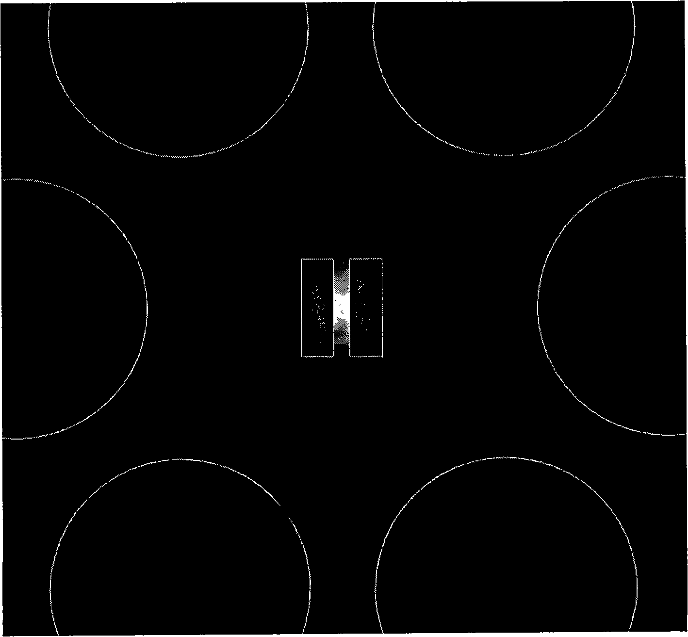
[0021] Refer to attached Figure 1~2 , a photonic crystal fiber based on the slit effect, with a cross-sectional structure such as figure 1 As shown, the base material 1 of the optical fiber is quartz, the refractive index at 1.55 μm is 1.45, and the nonlinear coefficient n 2 =2.6x10 -20 m 2 / W, the air holes 3 in the cladding are uniformly arranged in the base material 1 according to the equilateral triangle rule generally adopted by common photonic crystal fibers recognized in the art, and the distance between adjacent air holes is Λ=2 μm, and each air hole in the cladding The diameter of the hole 3 is d=0.8Λ. The two high-refractive-index materials 2 that form the slit 4 in the fiber core area and the base material 1 are silicon, and the refractive index at 1.55 μm is 3.46. The cross-section of each piece of high refractive index material 2 is a rectangle, the length of its long side is a=0.3Λ, the length of short side is b=0.1Λ, and the distance between the centers of ...

Embodiment 2

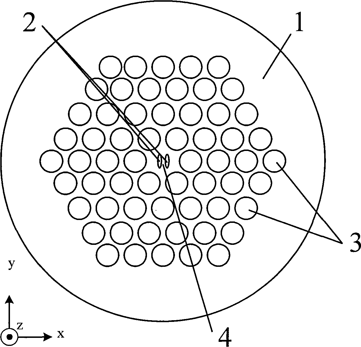
[0023] Refer to attached Figure 3-4 , another photonic crystal fiber based on the slit effect, with a cross-sectional structure such as image 3 As shown, the substrate material 1 of the optical fiber is highly nonlinear silicate glass Schott SF57, the refractive index at 1.55 μm is 1.8, and the nonlinear coefficient n 2 =4.1x10 -19 m 2 / W, the air holes 3 in the cladding are uniformly arranged in the base material 1 according to the equilateral triangle rule generally adopted by common photonic crystal fibers recognized in the art, and the distance between adjacent air holes is Λ=2 μm, and each air hole in the cladding The diameter of the hole 3 is d=0.8Λ. The two high-refractive-index materials 2 that form the slit 4 in the fiber core area and the base material 1 are silicon, and the refractive index at 1.55 μm is 3.46. The cross section of each piece of high refractive index material 2 is elliptical, its long axis is a=0.3Λ, its short axis is b=0.1Λ, and the distance b...


PUM

PropertyMeasurementUnit
diameteraaaaaaaaaa
refractive indexaaaaaaaaaa

Abstract

The invention discloses a photon crystal optical fiber, whose transect includes a fiber core and a cladding. The cladding is identical to the common photon crystal optical fiber, and is a peripheral area surrounding the fiber core and homogeneously distributed with identical structural airports. The airports are periodically arranged in the optical fiber base material, the dimension of the airports is the wavelength magnitude, every three adjacent airport units constitute a regular triangle. The fiber core is jointly constituted by an optical fiber base material locating at the center part of the optical fiber end-face and another solid material, wherein, the refractivity of the solid material is higher than that of the optical fiber base material, two blocks of solid material are symmetric distributed at the both sides of the optical fiber end-face center and the minimum distance of their outer margins should be smaller than 400nm in order to produce a narrow slit. The transect of the solid high-index material may be circular, elliptical shape, square or oblong; the diameter of the circular cross section, the minor axis diameter of the elliptical cross-section, the edge length of the square cross section, and the short edge length of the oblong cross section should be smaller than 400nm. By changing the fiber core structure of the photon crystal optical fiber, the invention uses the narrow slit to limit the light to spread in the nano-scale dimension low refractivity base material, thereby largely decreasing the effective model field area, and causing the photon crystal optical fiber to have ultra-high non-linearity and ultra-low limitation waste. The invention uses a simple and convenient manufacturing structure to resolve the problem in the prior photon crystal optical fiber technique, which is be difficult to implement ultra-high non-linear.

Description

Technical field [0001] The invention relates to a photonic crystal waveguide structure, in particular to a photonic crystal fiber with ultrahigh nonlinearity. Background technique [0002] Photonic crystal fiber is also called holey fiber or microstructure fiber. On the fiber end face, many regularly arranged air holes on the order of wavelength extend axially in the base material, and an air hole is missing in the center of the fiber, replaced by a solid fiber base material, or inserted with a high refractive index. Other materials other than the base material form the light-guiding core, while the peripheral air holes are uniformly arranged in the base material to form a cladding, and the light field is basically limited to the high refractive index area in the center. The principle of reflection guides light, so it is also called total internal reflection photonic crystal fiber. By adjusting the size of air holes in the cladding, the hole spacing, the size of the centra...

Claims


Application Information

Patent Timeline
Patent Type & Authority Applications(China)
IPC IPC(8): G02B6/02G02F1/355
Inventor 安琳郑铮李铮穆达瑟
Owner BEIHANG UNIV
Why Eureka
Try Eureka