Heat barrier coatings damage and its failure procedure acoustic emission real-time detection method

A technology of thermal barrier coating and real-time detection, which is applied in the processing of detection response signals and the use of sound waves/ultrasonic waves/infrasonic waves to analyze solids, etc., and can solve the problems of no reported research progress

Active Publication Date: 2008-10-15
XIANGTAN UNIV
View PDF0 Cites 42 Cited by
  • Summary
  • Abstract
  • Description
  • Claims
  • Application Information

AI Technical Summary

Problems solved by technology

However, in the face of complex and diverse failures of thermal barrier coatings, how to identify the failure mode, how to quantify the damage evolution, and how to determine the location of the damage source are huge problems faced by the current acoustic emission detection technology
In particular

Method used


Image

  • Heat barrier coatings damage and its failure procedure acoustic emission real-time detection method
  • Heat barrier coatings damage and its failure procedure acoustic emission real-time detection method
  • Heat barrier coatings damage and its failure procedure acoustic emission real-time detection method

Examples


specific Embodiment 1

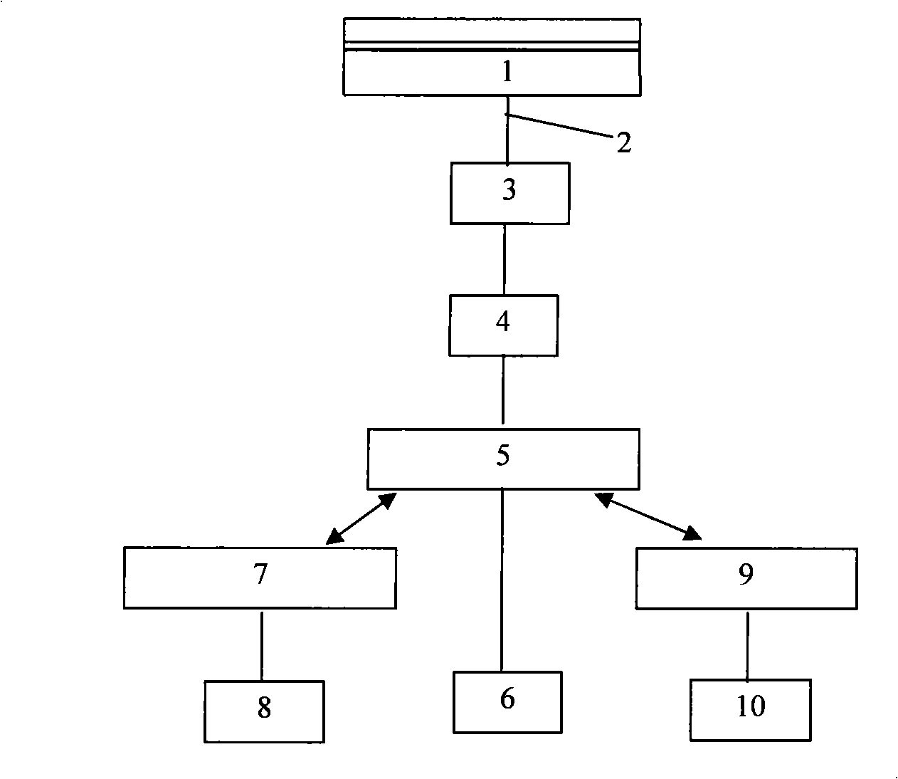
[0074] Acoustic emission real-time detection of tensile failure process of thermal barrier coatings at room temperature. The base material of the plasma sprayed thermal barrier coating sample is GH3030, and the intermediate transition layer material is NiCr 22 al 7 Y 0.2 (wt.%), the ceramic layer material is ZrO 2 -8wt.%Y 2 o 3 , the thicknesses of the intermediate transition layer and the ceramic layer are both about 200 μm. The experiment uses a universal tensile machine to load the sample. At the same time, two acoustic emission sensors are placed at both ends of the sample to receive the acoustic emission signal and collect it by the acoustic emission instrument. The sampling frequency is 1MHz, the sampling length is 1K, and the threshold is set 36dB. Tensile and acoustic emission tests were carried out on the uncoated base material and the thermal barrier coating, respectively.

[0075] During the tensile failure process, the distribution of acoustic emis...

specific Embodiment 2

[0080] Acoustic emission real-time detection of high temperature thermal fatigue failure of thermal barrier coatings. Acoustic emission detection experiment of high temperature thermal cycle was carried out on the thermal barrier coating. The thermal cycle included two processes of heating in a high temperature furnace at 800°C for 5 minutes and natural cooling in air for 10 minutes. In the experiment, the substrate surface of the thermal barrier coating sample was spot-welded with a platinum wire waveguide, and connected to the acoustic emission sensor through a mechanical device and an acoustic coupling medium to detect the damage of the thermal barrier coating during the entire thermal cycle.

[0081] The acoustic emission test results of thermal barrier coatings in the whole thermal fatigue found that the acoustic emission signal can appear in both the cooling stage and the heating stage, such as Figure 12 As shown, this shows that the damage of thermal barrier coati...


PUM

PropertyMeasurementUnit
Thicknessaaaaaaaaaa

Abstract

The invention discloses a real-time acoustic emission detection method for thermal barrier coating damage and a failure process thereof, which comprises the following steps that: a thermal barrier coating sample and an acoustic emission sensor are connected and coupled; a load is imposed on the thermal barrier coating sample, the acoustic emission sensor receives an acoustic wave signal emitted from the sample; the received acoustic wave signal is carried out through wavelet transform to obtain a wavelet energy spectrum coefficient distribution map, the damage pattern of the signal is determined according to the wavelet energy spectrum coefficient distribution map; the quantitative analysis of the damage is performed according to a relationship curve that the number of acoustic emission signal incidents of each damage pattern changes with the imposed load; a signal component under the scale where the maximum value of the wavelet energy spectrum coefficient is located is extracted, the time difference that the signal component reaches each sensor is calculated by a correlation analysis method, and the position of a damage source is determined by a time difference position method. The method can simply and quickly make a real-time detection to the damage of the thermal barrier coating material and also contributes to the accurate forecast to the life of the thermal barrier coating at the same time.

Description

technical field [0001] The invention relates to an acoustic emission real-time detection method for thermal barrier coating damage and failure process. Background technique [0002] Thermal barrier coating is a ceramic coating with very low thermal conductivity and excellent high temperature oxidation resistance. It is deposited on the surface of high temperature resistant metal parts or alloys through an adhesive layer, effectively connecting high temperature parts (alloys) with The high-temperature gas is isolated to reduce the surface operating temperature of high-temperature components, and protect high-temperature components from corrosion and erosion of high-temperature gas, greatly prolonging the service life of high-temperature components, thereby improving the gas temperature and thermal efficiency of aero-engines. It is a modern aero-engine It is one of the key technologies and has good application and development potential. Nitin, Gell and Jordan of the Universit...

Claims


Application Information

Patent Timeline
IPC IPC(8): G01N29/04G01N29/44
Inventor 周益春杨丽
Owner XIANGTAN UNIV
Why Eureka
Try Eureka