Eureka AIR delivers breakthrough ideas for toughest innovation challenges, trusted by R&D personnel around the world.

Spinning process of cellulose fibre and integration apparatus

A cellulose fiber and cellulose technology, applied in fiber processing, textiles and papermaking, filament/thread forming, etc., can solve problems such as uneven force, decreased mechanical properties of fibers, uneven fibers, etc., to achieve uniform strength and elongation long effect

Active Publication Date: 2008-10-22
CHINESE TEXTILE ACAD
View PDF2 Cites 16 Cited by
  • Summary
  • Abstract
  • Description
  • Claims
  • Application Information

AI Technical Summary

Problems solved by technology

In this invention, in order to be able to spin dense filament bundles, the thin stream extruded by the spinneret is cooled by cooling air in the air gap, but the method of blowing cooling air in this invention is used, due to the gap between the silk and the silk. The filaments are arranged in the same radial direction, which easily causes uneven force between the filaments, so that the resulting fibers are not uniform
[0007] In the Journal of Donghua University, Volume 29, No. 2, April 2003, the title "The Effect of Spinning Process on the Properties of Lyocell Cellulose Fibers with High Relative Molecular Mass" was published, and the paper showed through orthogonal experiments that the air gap and the number of spinneret holes will have a relatively large impact on the properties of cellulose. The larger the air gap length and the draw ratio, the higher the tensile strength and initial modulus of the fiber. At the same time, the number of spinneret holes has a greater impact on the fiber The mechanical properties of the spinneret also have a greater impact. The text shows that the more the number of spinneret holes, the flow path and internal stress of the spinning solution flowing through each hole are different, and the structure of each monofilament in the obtained fiber bundle is different. The larger it is, the lower the mechanical properties of the fiber will be caused

Method used


Image

  • Spinning process of cellulose fibre and integration apparatus
  • Spinning process of cellulose fibre and integration apparatus
  • Spinning process of cellulose fibre and integration apparatus

Examples


Embodiment 1

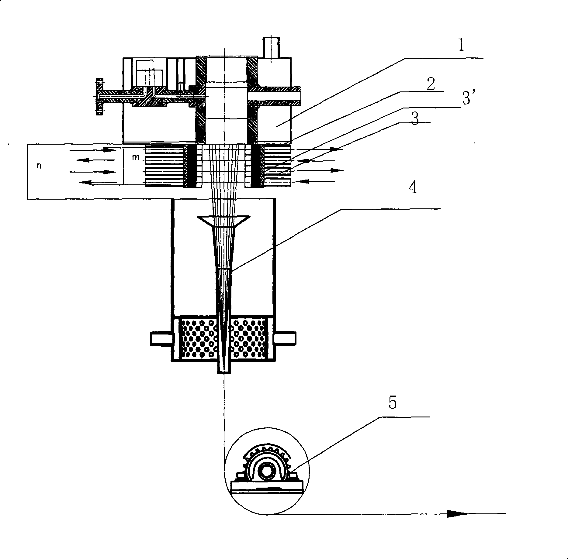
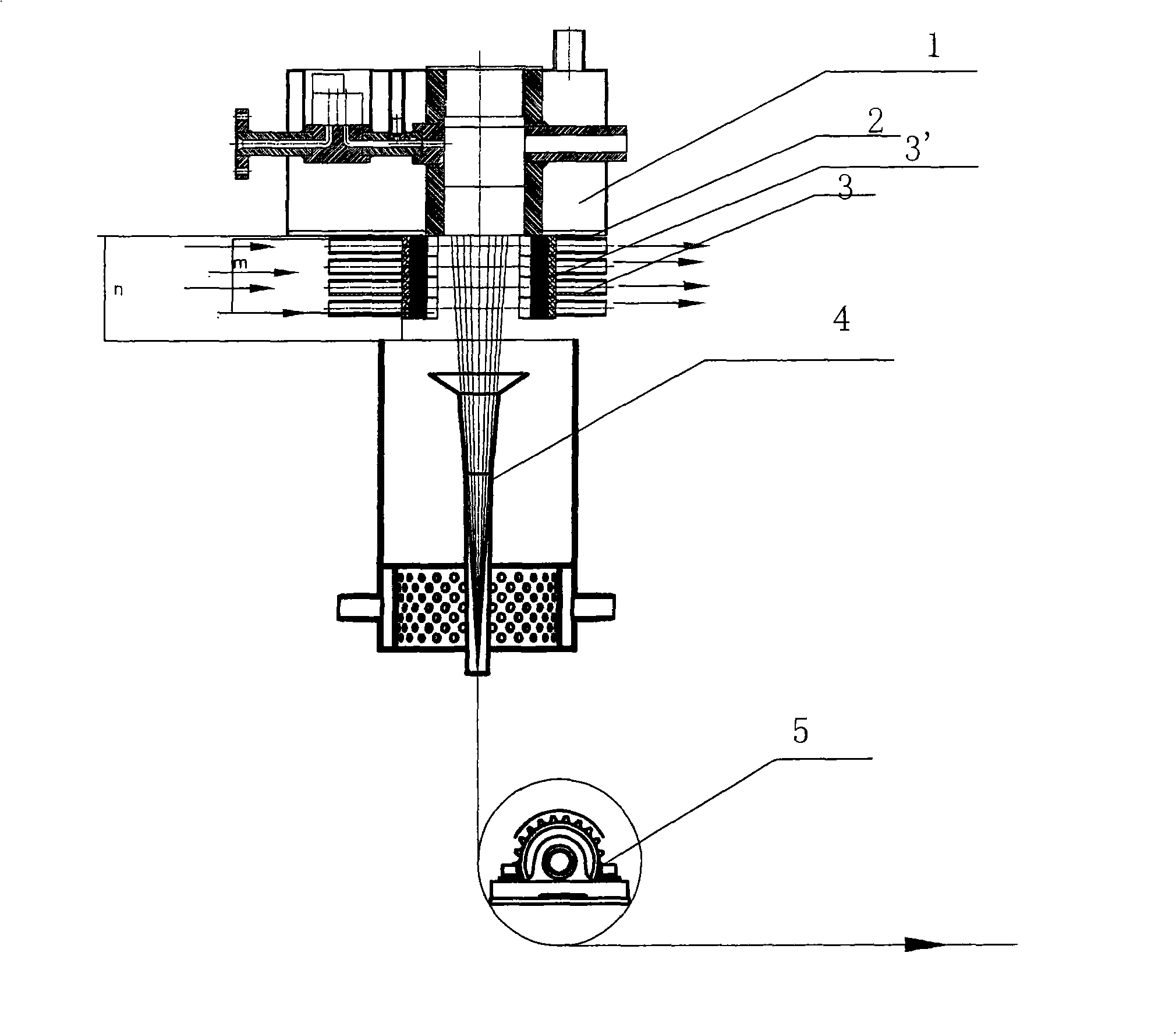
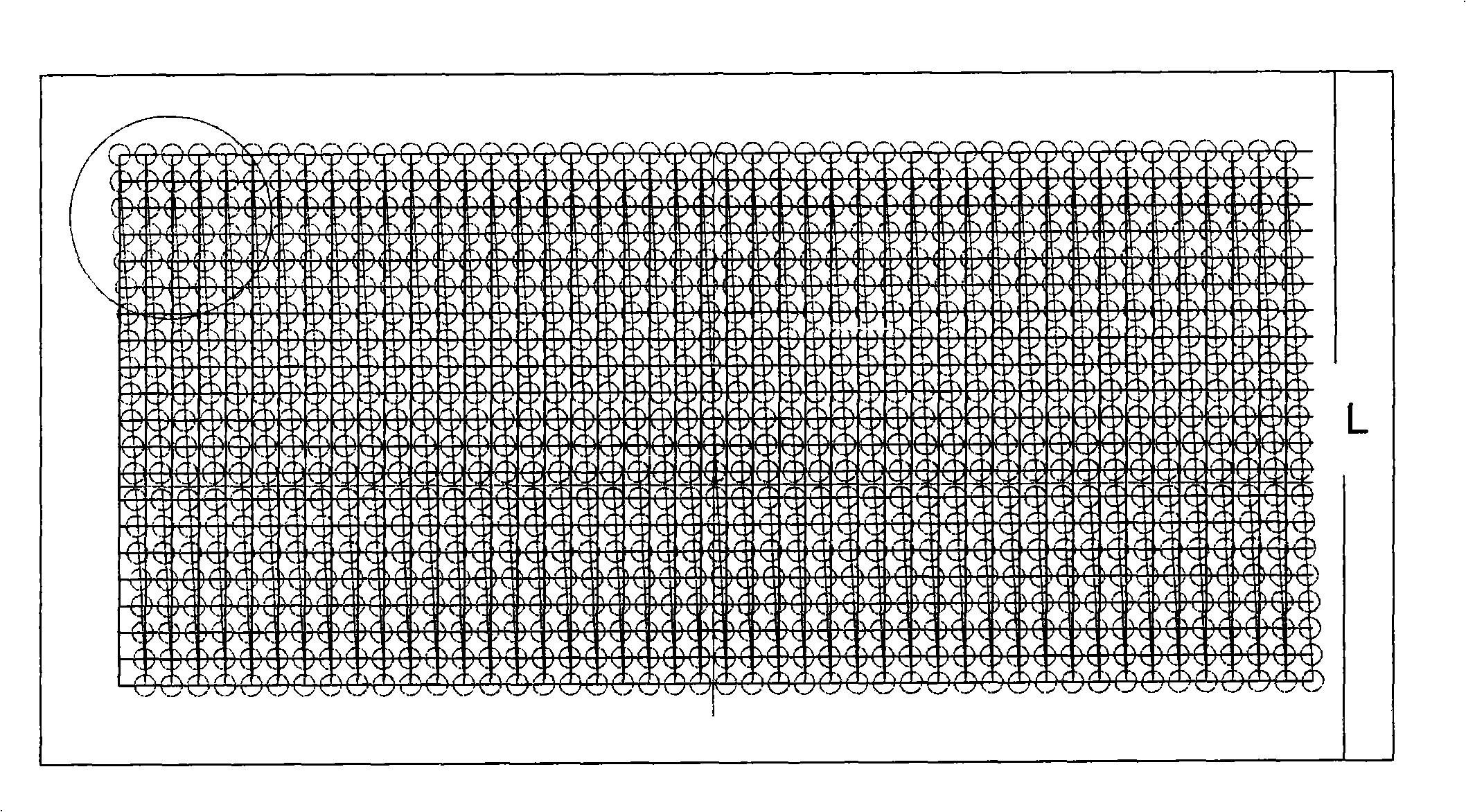
[0037] See attached figure 1, in this method, the spinning stock solution prepared by the continuous spinning stock solution preparation device, wherein the cellulose concentration is 9%, is extruded from the spinneret assembly 1, and passes through the spinneret 2, and the number of holes in the spinneret The number of spinneret holes is 2000, the diameter of the spinneret hole is 0.5mm, the ratio of the length of the spinneret hole to the diameter is 1, all the spinneret holes are arranged on a hole array, and the row of the hole array is parallel to the long side of the spinneret plate. The short side of the column and the spinneret is 0°, that is, parallel to the short side, and then passes through a section of air gap layer, the length n of the air gap layer here is 200mm, in this air gap layer, the cellulose fiber completes its In the stretching process, the cooling air at 20°C is issued from the cooling gas blowing device 3 located below the spinneret, and the tow is bl...

Embodiment 2

[0040] In this method, the spinning stock solution prepared by the continuous spinning stock solution preparation device, wherein the cellulose concentration is 11%, is extruded from the spinning assembly 1, and passes through the spinneret 2, and the number of holes in the spinneret is 2000, the diameter of the spinneret hole is 0.5mm, the ratio of the length to the diameter of the spinneret hole is 1, all the spinneret holes are arranged in a hole array, the row of the hole array is parallel to the long side of the spinneret, and the row It is 35° to the short side of the spinneret, and then passes through an air gap layer, where the length n of the air gap layer is 150mm. In this air gap layer, the cellulose fiber completes its stretching process, where , 10°C cooling nitrogen gas is issued from the cooling gas blowing device 3 located below the spinneret, blowing and sucking the tow in the form of two layers of laminar flow, and the cooling gas generating device includes tw...

Embodiment 3

[0043] In this method, the spinning stock solution prepared by the continuous spinning stock solution preparation device, wherein the cellulose concentration is 13.5%, is extruded from the spinning assembly 1, and passes through the spinneret 2, and the number of holes in the spinneret is 6000, the diameter of the spinneret hole is 0.25mm, the ratio of the length to the diameter of the spinneret hole is 2, all the spinneret holes are arranged in a hole array, the row of the hole array is parallel to the long side of the spinneret, and the row It is 15° to the short side of the spinneret, and then passes through a section of air gap layer, where the length n of the air gap layer is 100mm. In this gas gap section, the cellulose fiber completes its stretching process. Here At 10°C, the cooling air at 10°C is issued from the cooling gas blowing device 3 located below the spinneret. The cooling gas blowing device includes 6 layers of blowing ports and suction ports. The width is eq...


PUM

PropertyMeasurementUnit
pore sizeaaaaaaaaaa
elongation at breakaaaaaaaaaa

Abstract

The invention relates to a method for spinning cellulose fibers, comprising the following steps that: cellulose and organic solvent are mixed and dissolved, and mixture is obtained; the mixture enters into a section of air gap layer via a spinneret and ejected tows are blown and sucked by cooling air; the tows is brought into a precipitating bath via precipitating solution and led out by a spinning reel under the guidance of hauling equipment, wherein, the tows are blown and sucked by the cooling air by means of multi-layered laminar flow wind and the outlet velocity of the precipitating bath is between 20 and 150 meters per minute. The invention also relates to a device for completing the spinning method. By adoption of the spinning method and the spinning device, cellulose filaments or staple fibers obtained finally have uniform strength and elongation amount and the effect is also suitable for fibers with high or low size as well.

Description

technical field [0001] The invention relates to a cellulose fiber spinning method and integrated equipment. Background technique [0002] The fiber involved in the present invention is called Lyocell fiber, which is a kind of cellulose fiber produced by dissolving cellulose in an organic solvent and extruding the solution from a spinneret. [0003] The current production method of this kind of fiber is to mix cellulose in a solvent first, then heat the solution and extract part of the water under the condition of reduced pressure, so that the cellulose is dissolved in the solvent, and the cellulose in the solution is heated The continuous thin streams are extruded through the spinneret in the state, and these continuous thin streams are cooled by air and then enter the coagulation bath, so that the liquid cellulose can be coagulated to form continuous filaments. However, practice has proved that the prior art methods are unsatisfactory in the formation of filaments and the ...

Claims


Application Information

Patent Timeline
Patent Type & Authority Applications(China)
IPC IPC(8): D01D5/00D01D4/02D01D10/00
CPCD01F2/02D01D5/06D01D5/088
Inventor 骆强孙玉山林相来刘福安于若伟白玲徐成李晓俊陆伊伦
Owner CHINESE TEXTILE ACAD
Why Eureka
Eureka Blog
Learn More