Hot pipe EGR cooler

An EGR cooler and heat pipe technology, applied in indirect heat exchangers, machines/engines, lighting and heating equipment, etc., can solve the problems of reducing the degree of coolant vaporization, poor cooling effect, easy leakage, etc., and achieve horizontal free scalability Strong, reduce negative impact, buffer thermal stress effect

Inactive Publication Date: 2008-10-22
ZHEJIANG YINLUN MACHINERY
View PDF0 Cites 4 Cited by
  • Summary
  • Abstract
  • Description
  • Claims
  • Application Information

AI Technical Summary

Problems solved by technology

The main disadvantages are as follows: 1. The traditional exhaust gas cooling method uses engine coolant for cooling. Since the coolant in the steam state will cause serious cavitation to the engine cooling circuit, the engine coolant always exists in liquid form under working conditions. That is to say, the exhaust gas cooling is carried away by the temperature rise of the engine coolant, which has a poor cooling effect.
2. The conventional EGR cooler adopts shell-and-tube or plate-fin structure, and the compact structure is eas

Method used


Image

  • Hot pipe EGR cooler
  • Hot pipe EGR cooler
  • Hot pipe EGR cooler

Examples


Embodiment Construction

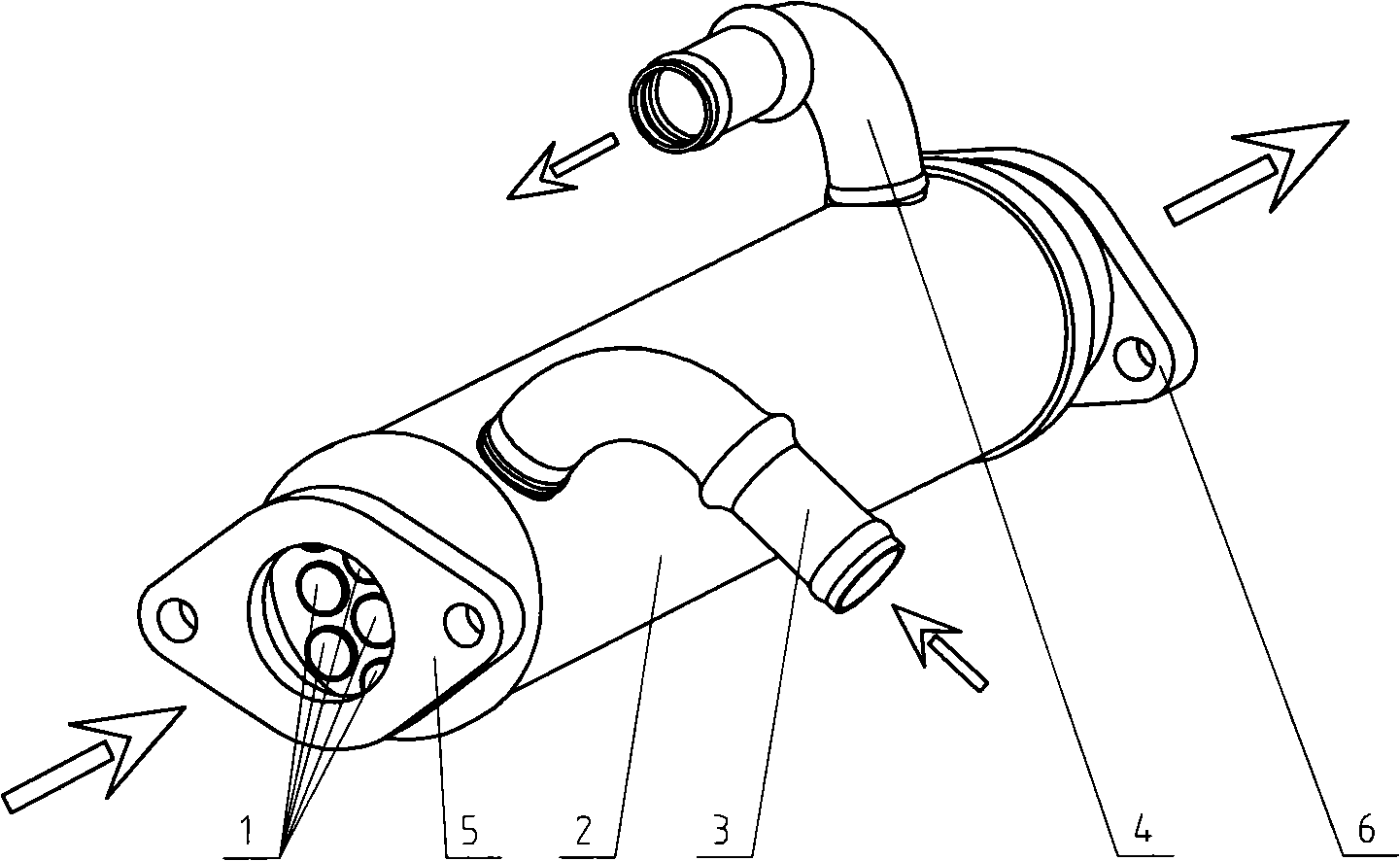
[0018] refer to figure 1 , this figure shows a traditional shell-and-tube EGR cooler, which includes a casing 2 with a coolant inlet 3 and an outlet 4 on the side, and a set of replacement parts arranged in parallel in the casing 2 with gaps between them. heat pipe1. The heat exchange tube 1 is connected to the exhaust gas recirculation circuit of the engine through an inlet flange 5 and an outlet flange 6 . And the engine coolant enters the inner cavity of the housing 2 from the coolant inlet 3 after being drawn out from the pipeline, then flows out from the coolant outlet 4, and is sent back to the engine cooling system by the pipeline. In this structure, in order to achieve a better heat exchange effect, the heat exchange tubes 1 are generally many and very thin. In the narrow tubes in the heat exchange tubes, the carbon formation on the inner wall of the tubes will easily block the tubes, and in severe cases, the tubes will be blocked. Disable the EGR cooler.

[0019] r...


PUM


Abstract

The invention discloses a heat pipe EGR cooler, mainly comprising a shell and a heat pipe, wherein, two ends of the shell are provided with a waste gas inlet and a waste gas outlet respectively; and the heat pipe consists of a heating section, a steam pipe, a condensing section and a condensation pipe which are communicated from beginning to end. The invention is characterized in that the heating section is arranged in the shell. The principle of the invention is to adopt the heat pipe technology to cool waste gas, which can ensure that the temperature of the waste gas is lower and can effectively relieve the influence of the waste gas to the power per liter of the engine on the premise of the same recirculation waste gas amount. Meanwhile, the heat pipe EGR cooler can effectively reduce the negative effect of the reduced heat exchanging efficiency caused by caking, and can effectively avoid a leaking occasion of welding lines of flange faces between the shell and the waste gas inlet and the waste gas outlet.

Description

technical field [0001] The invention relates to a gas cooling device, in particular to an exhaust gas recirculation cooler. It can be widely used in power plants using exhaust gas recirculation. Background technique [0002] With the increasingly stringent emission requirements, exhaust gas recirculation technology is increasingly used in power plants. The basic principle is that part of the exhaust gas discharged for the first time is cooled and then returned to the engine to effectively reduce the formation of nitrogen oxides in the exhaust gas. There are two types of coolers in the traditional exhaust gas recirculation (EGR) process: shell-and-tube type and plate-fin type. The main disadvantages are as follows: 1. The traditional exhaust gas cooling method uses engine coolant for cooling. Since the coolant in the steam state will cause serious cavitation to the engine cooling circuit, the engine coolant always exists in liquid form under working conditions. That is to ...

Claims


Application Information

Patent Timeline
IPC IPC(8): F02M25/07F28D15/02F02M26/32
CPCF28D15/0266Y02T10/121
Inventor 陆国栋安晓平陈子强张文锋张首都
Owner ZHEJIANG YINLUN MACHINERY
Why Eureka
Try Eureka