Technique for joint production of methanol and natural gas with methyl hydride containing synthesis gas

A technology for methane synthesis gas and natural gas, which is applied in the fields of gas fuel, organic chemistry, petroleum industry, etc., can solve the problems of large power consumption, large benefit impact, large investment, etc., and achieve the effect of increasing power consumption, increasing raw materials, and saving investment.

Active Publication Date: 2008-10-29
中国石油和化工勘察设计协会煤化工设计技术中心
0 Cites 26 Cited by

AI-Extracted Technical Summary

Problems solved by technology

Option 1 has been proved by factory practice that its process is complicated, the process is long, the power consumption of raw materials is high, and the product cost is high,...

Abstract

The invention belongs to the technology field of coal gasification comprehensive utilization and provides particularly a technique for preparing methanol and natural gas from methane-containing synthetic gas. The technique can overcome the shortcomings of a processing scheme of methanol in synthetic gas in the prior art; and the technique comprises the following steps: methane-containing synthetic gas is pressurized and then mixed with recycle gas from a methanol synthetic tower to synthesize methanol; the methanol-containing gas from the methanol synthetic tower is heat-exchanged with the gas mixture fed into the tower and cooled, and methanol is separated; a part of the methanol-separated gas as purged gas is introduced into a methane synthesizing device, and the other part is introduced into the methanol synthetic tower to continuously react to obtain natural gas after it is pressurized via circulator, recycled and then mixed with the methane-containing synthetic gas. The technique combines synthesis of methanol of high CH4 inert gas and production of natural gas by re-synthesizing methane from purged gas obtained from methanol synthesis. With the technique, two synthesis pressures and heat energy utilization can be combined together; thus making full use of the material and achieving the purposes of saved investment, energy and consumption and good benefit.

Application Domain

Technology Topic

Image

  • Technique for joint production of methanol and natural gas with methyl hydride containing synthesis gas
  • Technique for joint production of methanol and natural gas with methyl hydride containing synthesis gas
  • Technique for joint production of methanol and natural gas with methyl hydride containing synthesis gas

Examples

  • Experimental program(1)

Example Embodiment

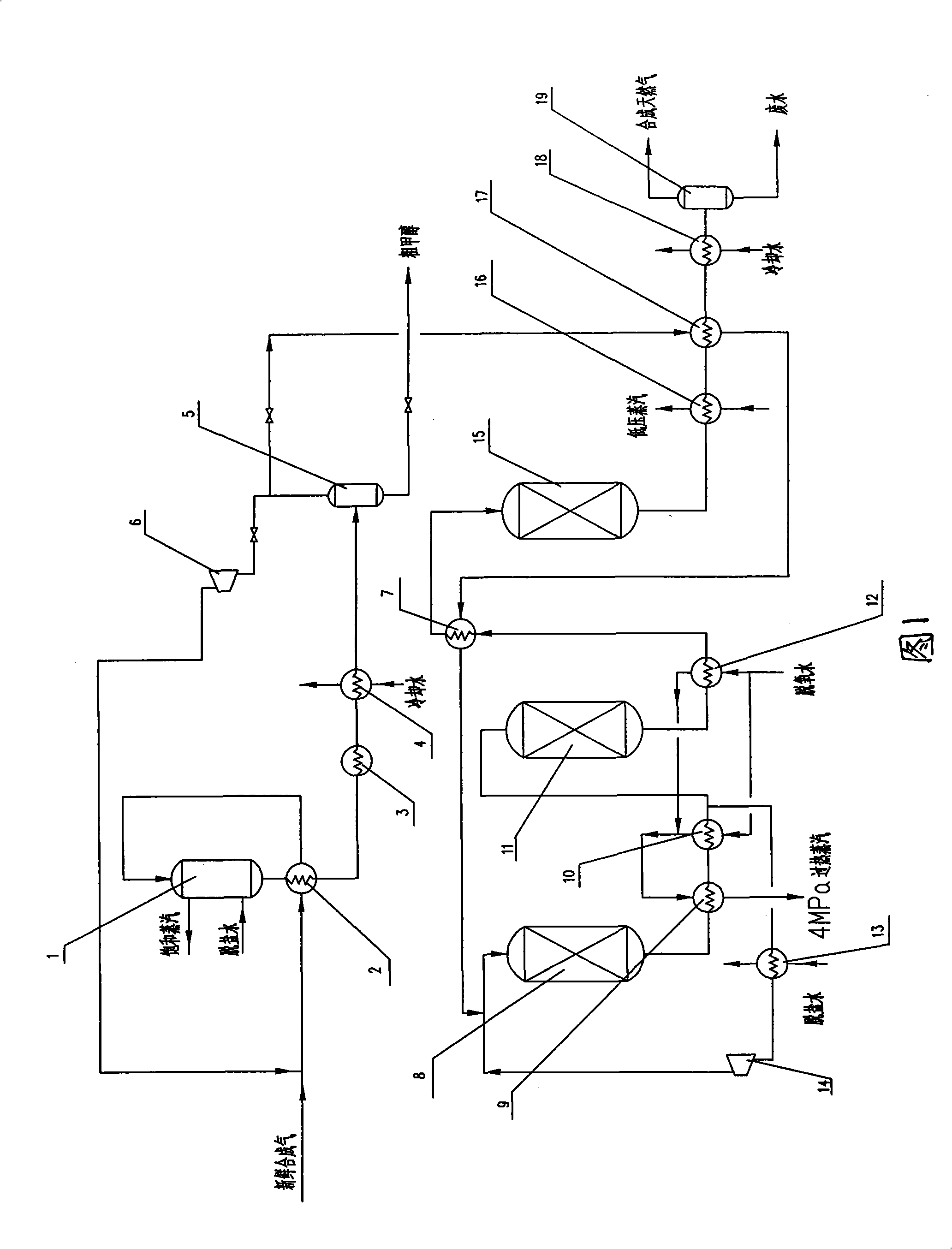
[0017] Below in conjunction with Fig. 1, the present invention is described in further detail, a kind of methane-containing synthesis gas co-production methanol and natural gas technology, methane-containing synthesis gas (H 2 , CO, CO 2 、CH 4 ) is pressurized to about 7MPa(a) with a synthesis gas compressor, and then mixed with the circulating gas from the methanol synthesis tower 1. The mixed gas passes through the gas-gas heat exchanger 2 to exchange heat to 220-230°C, and then enters the methanol synthesis Tower 1 synthesizes methanol, and the methanol-containing gas exiting methanol synthesis tower 1 and the mixed gas entering the tower exchange heat in gas-gas heat exchanger 2, then pass through air cooler 3 and water cooler 4 to finally cool the gas to 40°C, and methanol is condensed into The liquid is separated in the methanol separator 5, and part of the gas separated from the methanol enters the methane synthesis unit as a relaxation gas, and the other part is pressurized by the circulator 6, mixed with the synthesis gas containing methane and preheated to the required temperature. Enter methanol synthesis tower 1 again to continue reaction,
[0018] The purge gas from methanol synthesis reaction and separation of methanol is preheated to 180-190°C and mixed with the cycle gas from the first methanation reactor, then enters the first methanation reactor, and enters the catalytic bed at 240-250°C for reaction Methane is generated, and natural gas is finally obtained through the second and third methane reactors.
[0019] According to the different molar composition of syngas, determine the H in fresh gas 2 , CO, CO 2 、CH 4 The molar composition ensures the quality of methanol and natural gas. There is no purge gas emission in the whole process. The methanol synthesis cycle ratio is 3.5-4.5 and the molar composition of inert gas in the cycle gas is 25-35%.
[0020] According to the molar composition of the methanol purge gas, and according to the characteristics of the methane catalyst, the position of the synthetic natural gas cycler, that is, the methane synthesis cycler 14 shown in Fig. CO, H 2 , CO 2 conversion rate.
[0021] As shown in Figure 1, three methanation reactors are used, namely the first methanation reactor 8, the second methanation reactor 11, and the third methanation reactor 15, and the purge gas from methanol synthesis passes through The first methanation reactor 8, the second methanation reactor 11, and the third methanation reactor 15 synthesize methane. The methane synthesis cycler 14 forms a circulation loop with the first methanation reactor 8 and is located after the first waste heat boiler 10 .
[0022] The purge gas from methanol synthesis at 40°C, 6.5MPa(a) is preheated to 180-190°C and mixed with the cycle gas at 180-190°C, 6.5MPa(a), and then enters the first methanation reactor 8 jacket, 240 ~250℃ into the catalytic bed, H 2 , CO, CO 2 The following reactions occurred:
[0023]
[0024]
[0025]
[0026] The gas temperature 550°C exiting the first methanation reactor 8 enters the steam superheater 9 to superheat the 4.0MPa(a) saturated steam to 450°C, and then enters the first waste heat boiler 10 to generate 4.0MPa(a) saturated steam. After the methane-containing gas from the first waste heat boiler 10 exchanges heat with the gas at the outlet of the circulator, the gas temperature drops to 180°C, enters the methane synthesis circulator 14 for pressurization, mixes it with the exhaust gas from methanol synthesis, and then enters the second A methane synthesis reactor with 8 jackets, and the temperature rises to 240-250°C.
[0027] Another stream of methane-containing gas exiting the first waste heat boiler 10 passes through the boiler feed water preheater, then drops to 180°C and enters the jacket of the second methane reactor 11, enters the catalyst bed at about 240-250°C, and exits the second methane The gas temperature in the methanation reactor 11 is about 360°C and enters the second waste heat boiler 12 to produce 4.0MPa(a) saturated steam, and then enters the third methanation synthesis reactor 15 at about 230°C after heat exchange with the methanol purge gas, and the synthetic natural gas that comes out After exchanging heat with the methanol purge gas preheater 17, it passes through the boiler feed water preheater or the low-pressure waste boiler 16 to produce 0.5MPa(a) saturated steam.
[0028] The second and third methane synthesis reactors mainly have the following chemical reactions.
[0029]
[0030]
[0031]
[0032] After a three-stage reactor synthesis, the conversion rate of CO is nearly 100%, and the H 2 99% conversion rate, CO 2 The conversion rate was 91%. The low calorific value of natural gas reaches 30982kJ/Nm 3 (7400kcal/Nm 3 ).

PUM

no PUM

Description & Claims & Application Information

We can also present the details of the Description, Claims and Application information to help users get a comprehensive understanding of the technical details of the patent, such as background art, summary of invention, brief description of drawings, description of embodiments, and other original content. On the other hand, users can also determine the specific scope of protection of the technology through the list of claims; as well as understand the changes in the life cycle of the technology with the presentation of the patent timeline. Login to view more.

Similar technology patents

Classification and recommendation of technical efficacy words

  • Reduce consumption
  • Less investment

Ecological repair method for shallow water lake shore zone

InactiveCN101486512AEcological restoration cycle is shortLess investmentSustainable biological treatmentBiological sludge treatmentShort cycleWater environment
Owner:江苏省滆湖渔业管理委员会办公室
Why Eureka
Try Eureka