RFID reader-writer antenna capable of overlapping high-frequency and ultrahigh frequency as well as microwave frequency band

An ultra-high frequency and microwave technology, applied in the field of electronics, which can solve the problems of rare reader antennas and inconvenient application.

Inactive Publication Date: 2008-11-05
BEIJING UNIV OF POSTS & TELECOMM
View PDF2 Cites 25 Cited by
  • Summary
  • Abstract
  • Description
  • Claims
  • Application Information

AI Technical Summary

Problems solved by technology

The traditional antenna can only work in a single frequency band. The reader using this antenna can only read the tags of a specific frequency band. If you want to read the tags working in different frequency bands, you need multiple readers,

Method used


Image

  • RFID reader-writer antenna capable of overlapping high-frequency and ultrahigh frequency as well as microwave frequency band
  • RFID reader-writer antenna capable of overlapping high-frequency and ultrahigh frequency as well as microwave frequency band
  • RFID reader-writer antenna capable of overlapping high-frequency and ultrahigh frequency as well as microwave frequency band

Examples


Embodiment Construction

[0030] The present invention will be further described below in conjunction with the embodiments and accompanying drawings.

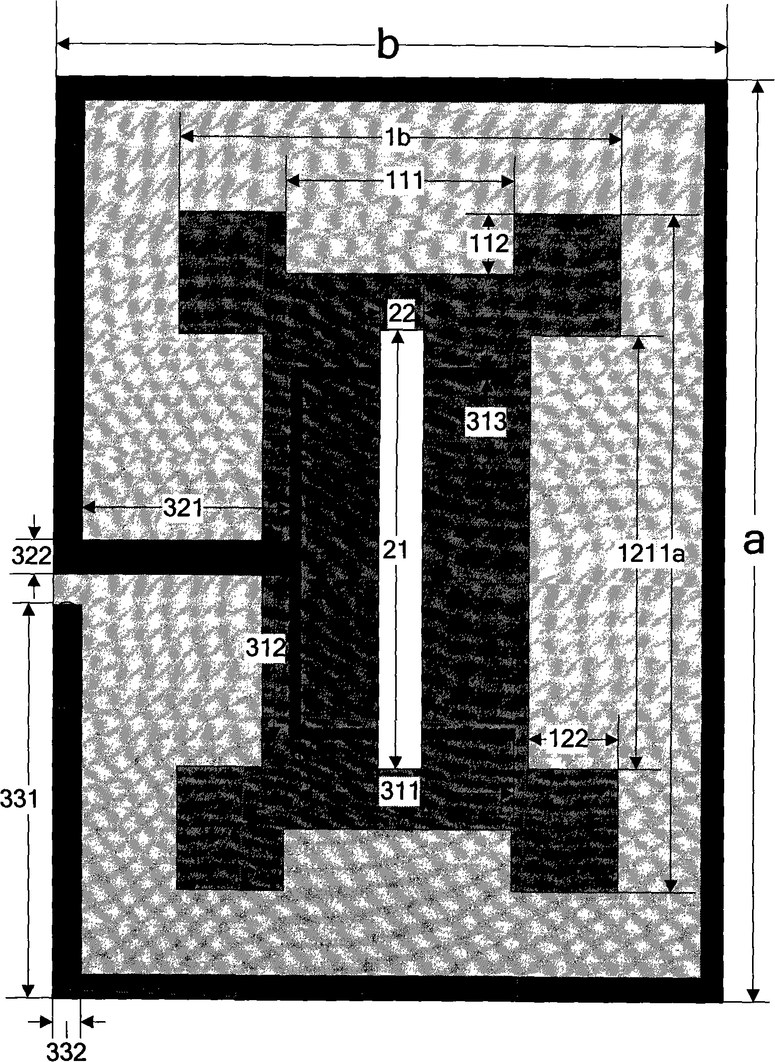
[0031] figure 1 It is a schematic top view of the structure of the embodiment of the present invention;

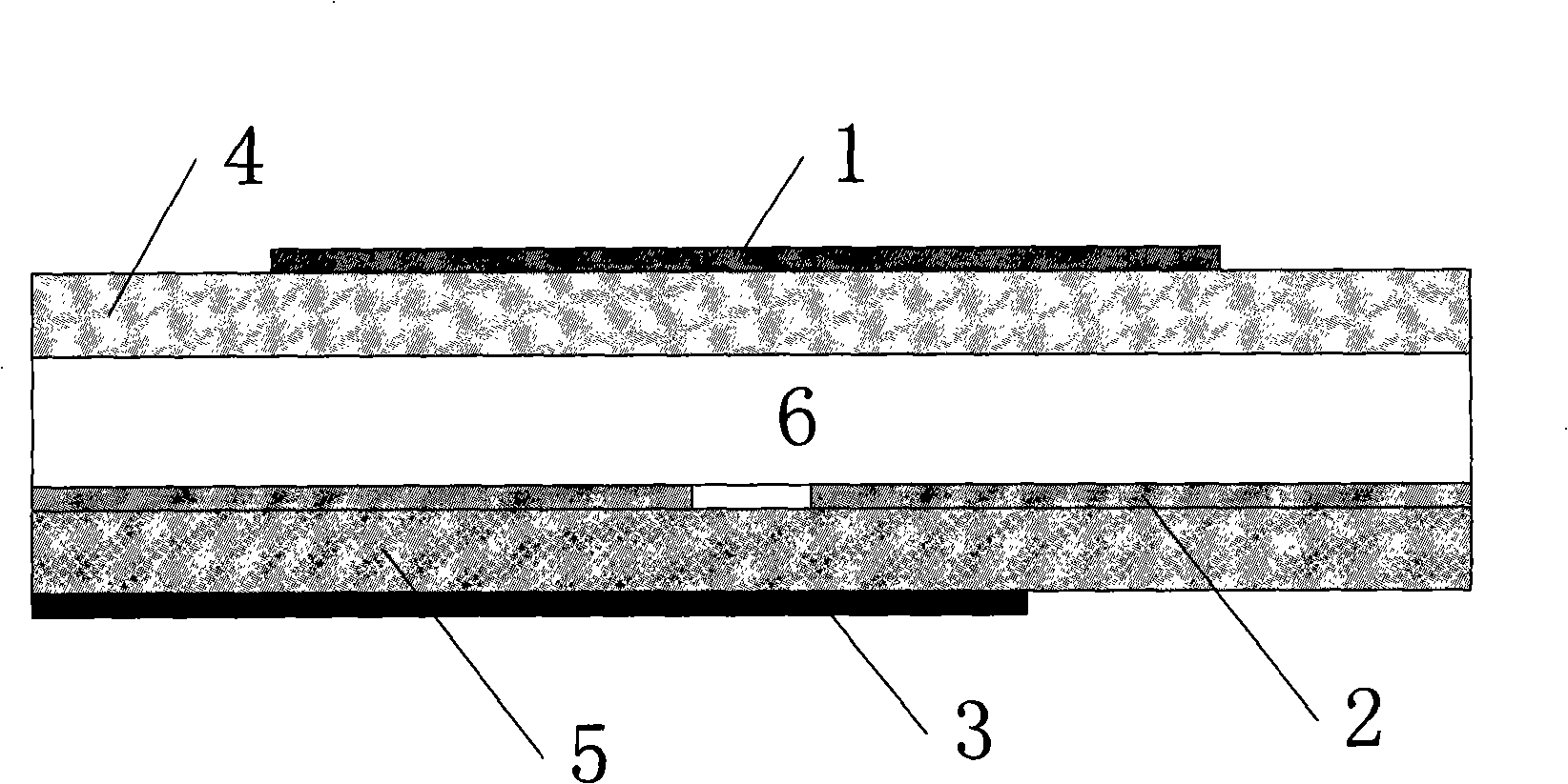
[0032] figure 2 It is a schematic side view of the structure of an embodiment of the present invention;

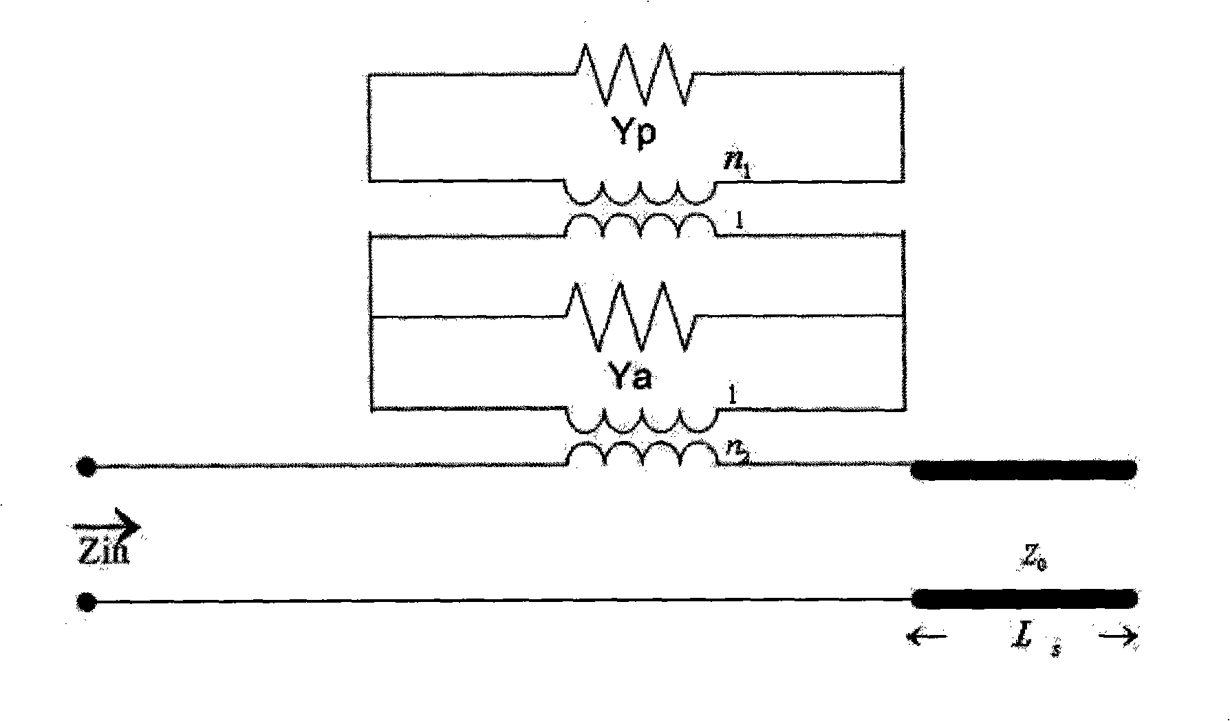
[0033] image 3 is a coupling equivalent circuit diagram of an embodiment of the present invention;

[0034] Figure 4 is the return loss simulation result diagram corresponding to the embodiment of the present invention;

[0035] Figure 5is a schematic diagram of the simulation gain corresponding to the embodiment of the present invention;

[0036] Figure 6 It is the Q value curve diagram of the high frequency band antenna corresponding to the embodiment of the present invention.

[0037] In the picture:

[0038] 1-Radiation unit 2-Grounding plate 3-Coupling and feeding unit 4-Dielectric plate 15-Double-sided metal dielectric plate...


PUM


Abstract

A three frequency band RFID reader-writer antenna used for a high frequency (HF) and a ultra high frequency (UHF) and a microwave (MW) is provided, specially relates to an antenna used in the laminated flat technology, composed of dielectric plates 1 and 2, a radiating element, an air layer, a ground plate, a coupling and feeding unit. The radiating element is arranged above the dielectric plate 1 grooving along the edge. The ground plate is arranged on one side of the dielectric plate 2 with a gap arranged at the middle, which is fed with the power to the radiating element through the gap. The air layer is arranged between the dielectric plates 1 and 2, adjusting the working bandwidth of the antenna through adjusting the thickness of the air layer and the size of the gap. The electromagnetic coupling and feeding unit is arranged on the other side of the dielectric plate 2 composed of a circle loop and a bicomponent microstrip line, wherein the circle loop provides the HF working performance to the antenna, and the bicomponent microstrip line controls the matching performance of the UHF and the MW. The invention has the characteristics of wider working bandwidth and the high gain, which is suitable for the antenna application of the three frequency band RFID reader-writer.

Description

technical field [0001] The invention belongs to the field of electronic technology and relates to an RFID reader antenna technology covering three frequency bands, high frequency (HF), ultra high frequency (UHF) and microwave (MW) frequency bands. The invention relates more particularly to antennas for stacked patch technology. Background technique [0002] With the increasing progress of modern society and the huge demand in the field of information management, RFID technology has been gradually applied to many industries, such as logistics and supply chain management, anti-counterfeiting and security control, traffic management and control, production management, etc. In the RFID system, the antenna plays a key role in realizing the data communication process, so the antenna design is the key to the application of the entire RFID system. With the rapid development of modern wireless communication technology, the requirements for antenna technology are getting higher and h...

Claims


Application Information

Patent Timeline
IPC IPC(8): H01Q1/38H01Q5/00H01Q13/08H01Q7/00
Inventor 李秀萍杜挺
Owner BEIJING UNIV OF POSTS & TELECOMM
Why Eureka
Try Eureka