
Process for production of fuel cell separators and fuel cells

A fuel cell and manufacturing method technology, applied to fuel cell parts, fuel cells, solid electrolyte fuel cells, etc., can solve problems such as inability to discharge smoothly, water retention, reduction in electromotive force, etc., and achieve stable electromotive force and excellent discharge performance. , the effect of high wettability

Inactive Publication Date: 2008-11-12
DIC CORP
View PDF5 Cites 0 Cited by
  • Summary
  • Abstract
  • Description
  • Claims
  • Application Information

AI Technical Summary

Problems solved by technology

[0020] As shown above, since it is necessary to solve the problem that the generated water stays in the gas flow path and cannot be discharged smoothly, resulting in a decrease in electromotive force, it is required to provide a separator that has a rib structure that can ensure electrical conductivity and can impart stable affinity. Water-based

Method used


Image

  • Process for production of fuel cell separators and fuel cells

Examples


Embodiment 1

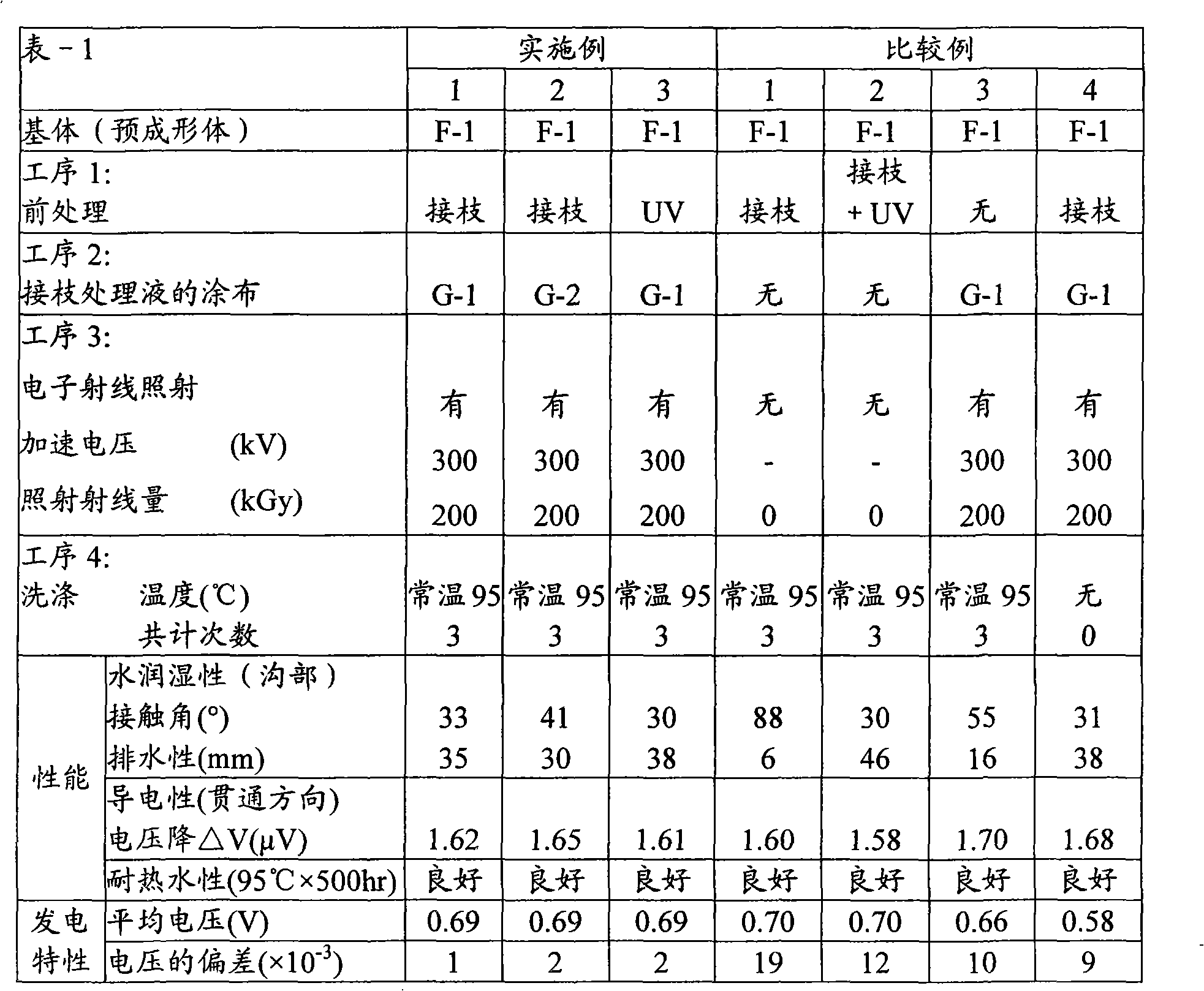
[0106] The molded product F-1 obtained in Preparation Example 2 was pretreated by blasting the electrode portion (groove portion) with a blasting device. The molded article was uniformly coated with graft treatment liquid G-1 treated with nitrogen blowing on the channel grooves of the electrode part in the atmosphere, and dried at room temperature for about 10 minutes. Then, electron beams were irradiated at room temperature in a nitrogen atmosphere at an accelerating voltage of 300 kV and an irradiation dose of 200 kGy. In order to remove unreacted components, it was washed twice with ion-exchanged water at room temperature, and then warmly washed with ion-exchanged water at 95° C. for 3 hours. Finally, after washing with ion-exchanged water at room temperature, it was dried at room temperature for 24 hours. In this way, fuel cell separator H-1 was obtained. The separator was evaluated for water wettability, electrical conductivity, and hot water resistance of the flow chan...

Embodiment 2

[0108] The same operation as in Example 1 was performed except that the graft treatment liquid G-2 was used instead of the graft treatment liquid G-1. In this manner, fuel cell separator H-2 was obtained. For this separator, as in Example 1, the water wettability, electrical conductivity, and hot water resistance of the flow path grooves in the electrode portion, and the operating characteristics of the fuel cell were evaluated. The evaluation results thereof are shown in Table-1.

Embodiment 3

[0110] Instead of blasting, the same operation as in Example 1 was performed except that the surface treatment was performed for 30 minutes in a UV ozone treatment apparatus. In this manner, fuel cell separator H-3 was obtained. For this separator, also in the same manner as in Example 1, the water wettability, electrical conductivity, and hot water resistance of the electrode part flow channel grooves, and the operating characteristics of the fuel cell were evaluated. The evaluation results thereof are shown in Table-1.


PUM


Abstract

A process for producing fuel cell separators which comprises imparting hydrophilicity to at least part of a preform made either of a thermosetting resin or of both a thermosetting resin and a carbonaceous material, characterized by conducting at least the following steps (1), (2), (3) and (4) or the steps (1), (3), (2) and (4) in this order: the step (1) of subjecting the preform to treatment for enhancing the affinity for a fluid of a radical -polymerizable monomer having a hydrophilic group and / or a functional group convertible into a hydrophilic group, the step (2) of applying the fluid to the treated surface, the step (3) of irradiating the resulting treated surface with a radiation, and the step (4) of washing the fuel cell separator obtained through the steps (1) to (3).

Description

technical field [0001] The present invention relates to a method for producing a fuel cell separator with improved surface hydrophilicity. In particular, it relates to a method of manufacturing a fuel cell separator in which the hydrophilicity of a groove portion of a gas flow path is improved, and a fuel cell having a stable output. Background technique [0002] A fuel cell is a device in which electrodes receive a supply of fuel to directly convert chemical energy contained in the fuel into electrical energy, and is known as a power generation method with high energy conversion efficiency. In such a fuel cell, the cathode receives the supply of fuel gas containing hydrogen and the anode receives the supply of oxidizing gas containing oxygen through the gas flow path formed in the separator. Generate water. [0003] Usually, the produced water vaporizes into the oxidizing gas supplied to the anode side, and is discharged out of the fuel cell together with the oxidizing ga...

Claims


Application Information

Patent Timeline
Patent Type & Authority Applications(China)
IPC IPC(8): H01M8/02H01M8/10
CPCY02E60/50H01M8/0228H01M8/0213H01M2008/1095H01M8/04171H01M8/0221H01M8/0226Y02P70/50H01M8/02
Inventor 安村隆志滨田健一兼松孝之川村孝
Owner DIC CORP
Learn More