
Method and apparatus for processing of substrates having laser-written trench contacts, in particular solar cells

A technology of solar cells and grooves, applied in the field of processing base parts, can solve the problems of high process cost and damage

Inactive Publication Date: 2010-11-17
GEBR SCHMID GMBH & CO
View PDF8 Cites 0 Cited by
  • Summary
  • Abstract
  • Description
  • Claims
  • Application Information

AI Technical Summary

Problems solved by technology

The disadvantage of this approach is that the process cost is high, and high temperature treatment may cause SiN x damage, or cause negative changes in the silicon structure, and the annealing process means that the aluminum backside of the base part is again loaded

Method used


Image

  • Method and apparatus for processing of substrates having laser-written trench contacts, in particular solar cells
  • Method and apparatus for processing of substrates having laser-written trench contacts, in particular solar cells

Examples


Embodiment Construction

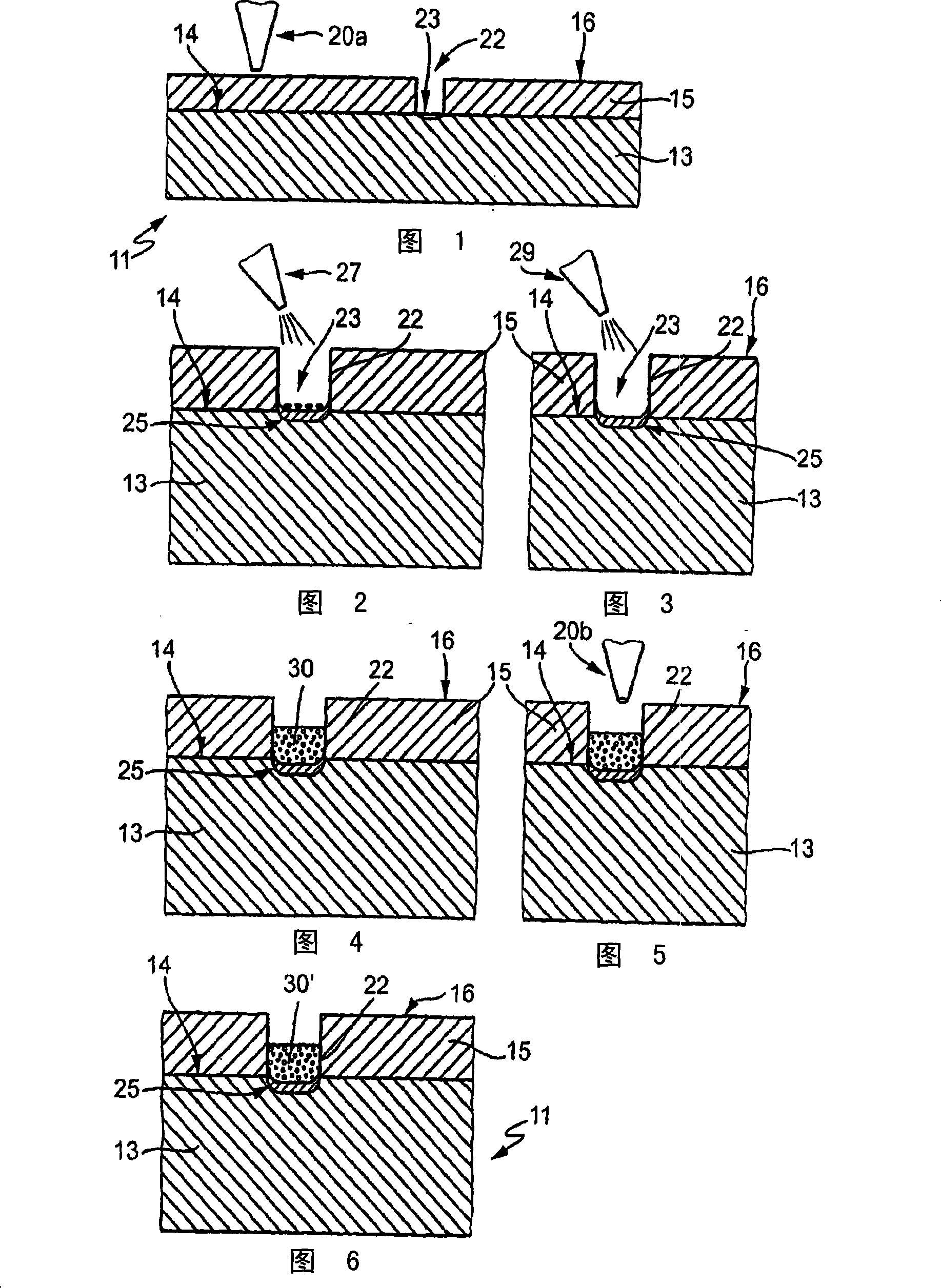
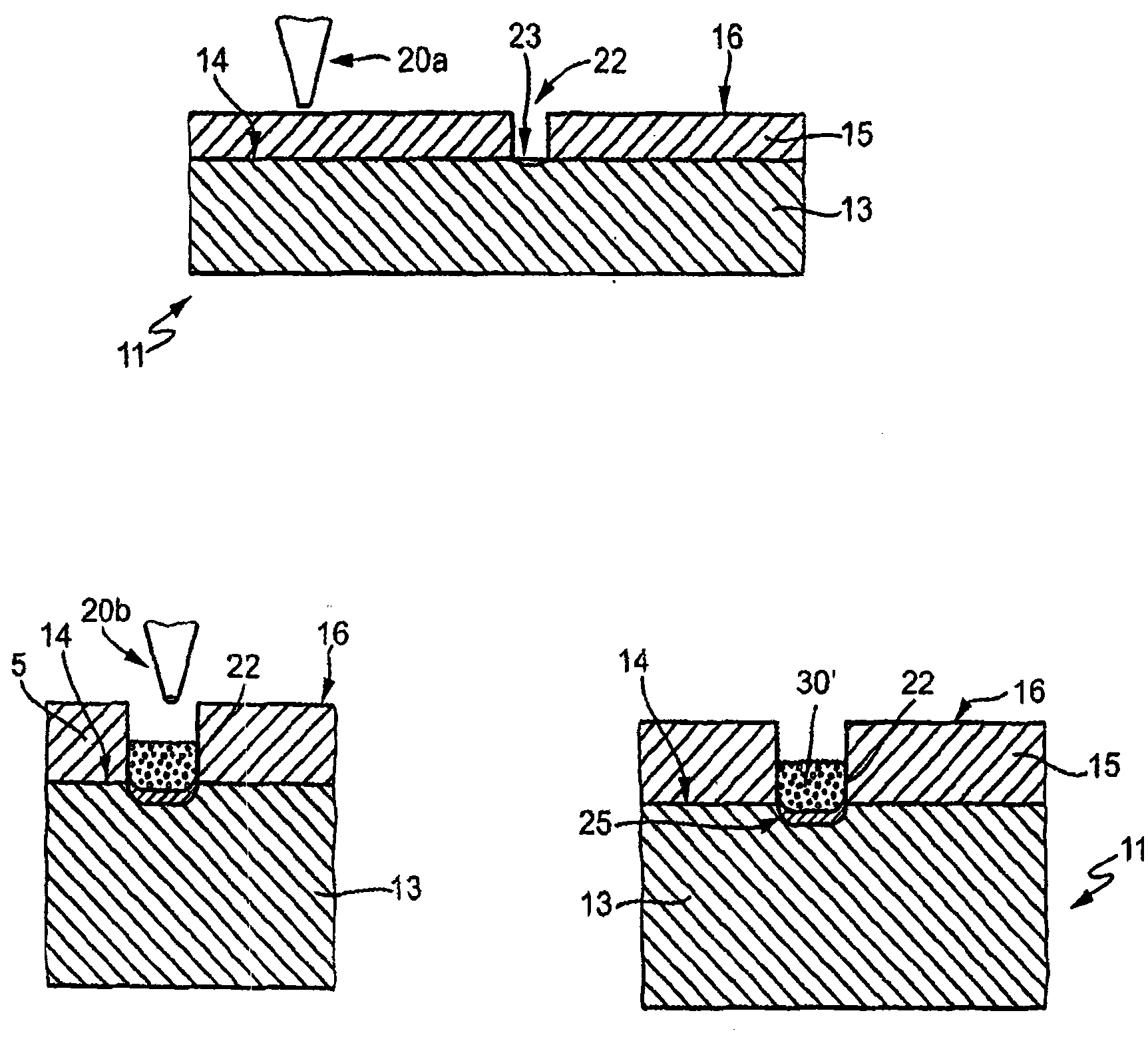
[0023] figure 1 Shown is a solar cell 11 with a silicon active layer 13 . The top surface 14 of the active layer 13 is coated with an anti-reflection layer 15 which may consist, for example, of SiNx. This structure has long been known to professionals.

[0024] Such as figure 1 As shown, the top surface 16 of the anti-reflection layer 15 is irradiated with a laser 20a, and a groove 22 is processed therein. A plurality of mutually parallel grooves 22 are processed at a certain distance, just like the contacts already existing on the solar cell 11 . from figure 1 It can be seen from the figure that the trench bottom 23 is roughly located in the area where the top surface 14 of the active layer 13 is located. This means that the entire anti-reflection layer material will be removed in the trench 22 by the width of the trench.

[0025] The laser can be set as follows:

[0026] The pulse energy is 25-80μJ / per pulse, the focal spot diameter is about 22μm, and the power per...


PUM


Abstract

In order to process a silicon wafer for a solar cell (11), an anti-reflective coating (15) on an active silicon layer (13) can be provided with trenches (22), for example by means of a laser (20a). The possibility of damage to the upper face (14) of the active layer (13) by the laser (20a) can be avoided by introducing a contact and doping material (30) into the trench (22). This material contains nickel for the contact function and phosphorus for the doping function. Heating of the contact and doping material (30), for example by means of a second laser (20b), results in doping of the adjacent area (25) of the active layer (13). This can thus be repaired and, in addition, a very low contact resistance can be produced to the finished contact (30').

Description

technical field [0001] The invention relates to a method for processing a substrate, in particular a solar cell, in which an active layer with an antireflective layer is arranged on the top side of the substrate. Furthermore, the invention also relates to a device for carrying out the method. Background technique [0002] For example, when solar cells are manufactured or processed on silicon wafers, these cells have an active layer made of silicon on which the contact contacts on the front side have to be coated. In addition, in order to improve the efficiency of the solar cell, an anti-reflection layer is applied. As far as the process flow is concerned, the anti-reflection layer should be applied first, and then the contact contacts should be set. [0003] In addition, grooved buried gate solar cells are already known, i.e. using a laser to pass through the SiN x The anti-reflection layer produces grooves with a depth of 20-30 μm. The trenches are cleaned and then re-d...

Claims


Application Information

Patent Timeline
Patent Type & Authority Patents(China)
IPC IPC(8): H01L31/0224H01L31/0216H01L27/142
CPCH01L31/186H01L31/022425H01L31/02167Y02E10/52Y02E10/50Y02P70/50
Inventor C·施米德
Owner GEBR SCHMID GMBH & CO
Learn More