High-temperature combustion-supporting device and special combustion device for inverse combustion type biomass fuel

A biomass fuel and combustion device technology, applied in the combustion chamber, combustion method, combustion equipment and other directions, can solve the problems of black smoke, unsuitable use of biomass fuel, dust pollution, etc., to reduce investment and be beneficial to environmental protection , the effect of stable combustion

Inactive Publication Date: 2008-12-03
HENAN DERUN BOILER
View PDF0 Cites 9 Cited by
  • Summary
  • Abstract
  • Description
  • Claims
  • Application Information

AI Technical Summary

Problems solved by technology

However, the structure of most small boilers is not suitable for the u

Method used


Image

  • High-temperature combustion-supporting device and special combustion device for inverse combustion type biomass fuel
  • High-temperature combustion-supporting device and special combustion device for inverse combustion type biomass fuel
  • High-temperature combustion-supporting device and special combustion device for inverse combustion type biomass fuel

Examples


Embodiment 1

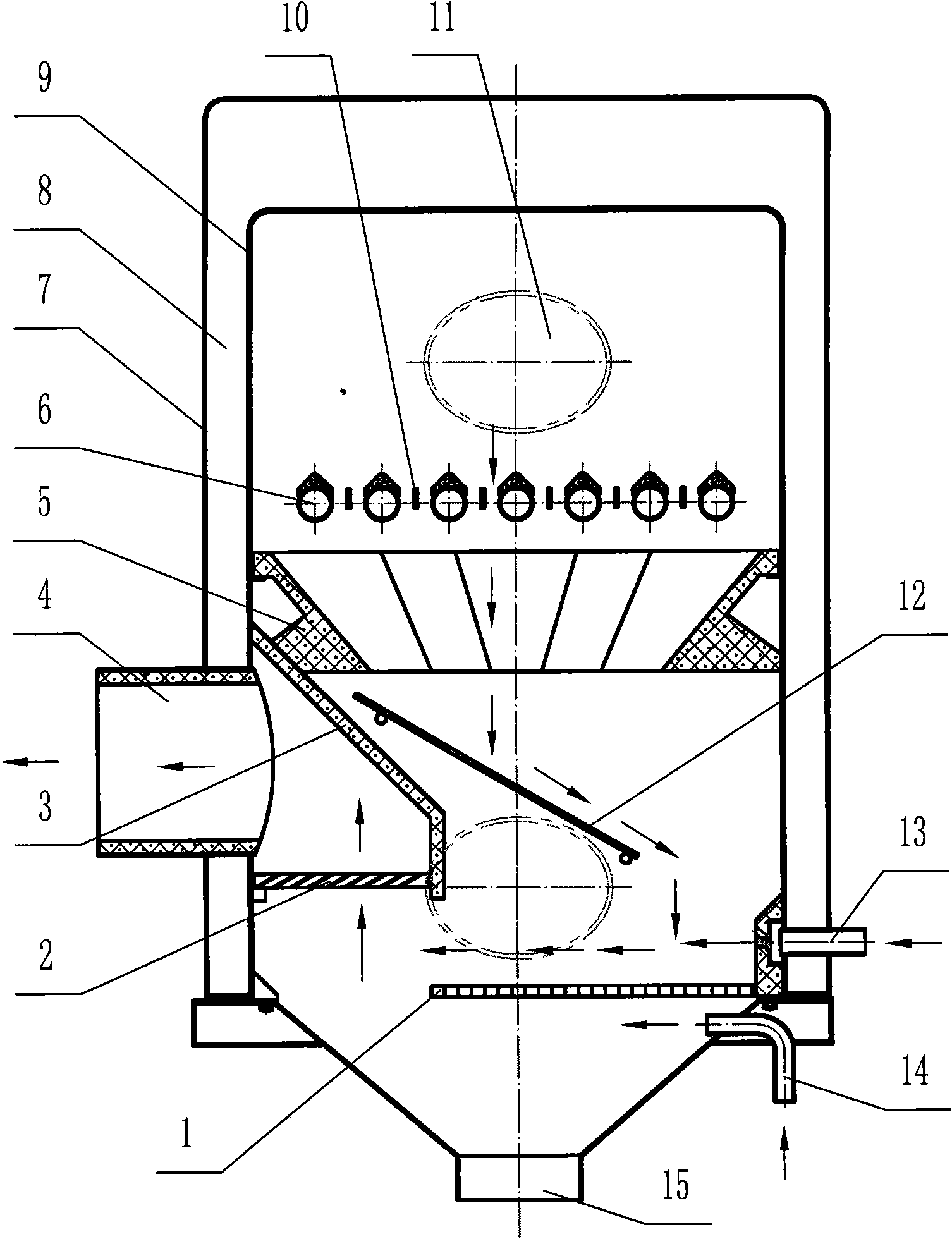
[0037] Embodiment one: see figure 1 ,Image 6- Figure 8 , Figure 11-Figure 15 , in the figure, a water jacket 8 and an outer shell 7 are provided on the surrounding surface and the top surface of the inner shell 9 of the special combustion device for backfired biomass fuel, and the upper part of the chamber surrounded by the inner shell 7 is the furnace, and the lower part is the ash In the slag chamber, the upper grate 6 and the lower grate 1 are arranged in the furnace, and the body wall of the inner shell 9, the water jacket 8 and the body wall of the outer shell 7 are respectively provided with a feeding port 11 and a high-temperature flue gas outlet 4. The port 11 is set on the upper part of the surrounding surface of the inner shell 9; the lower part of the ash chamber is provided with an ash discharge port 15, and the furnace between the upper grate 6 and the lower grate 1 is respectively provided with a high-temperature burner 5 and a hanging grate 12 , the inner sh...

Embodiment 2

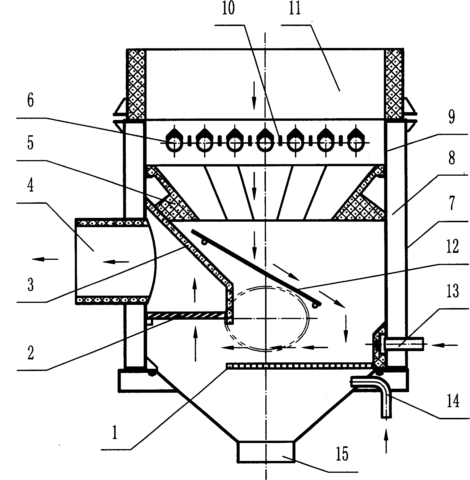
[0043] Embodiment two: see figure 2 , the number in the figure is the same as that of Embodiment 1, and the representative meaning is the same, and the same parts will not be repeated. The difference is that a water jacket 8 and an outer shell 9 are arranged on the surrounding surface of the inner shell 9, and the feed inlet 11 is arranged on On top, open feed.

Embodiment 3

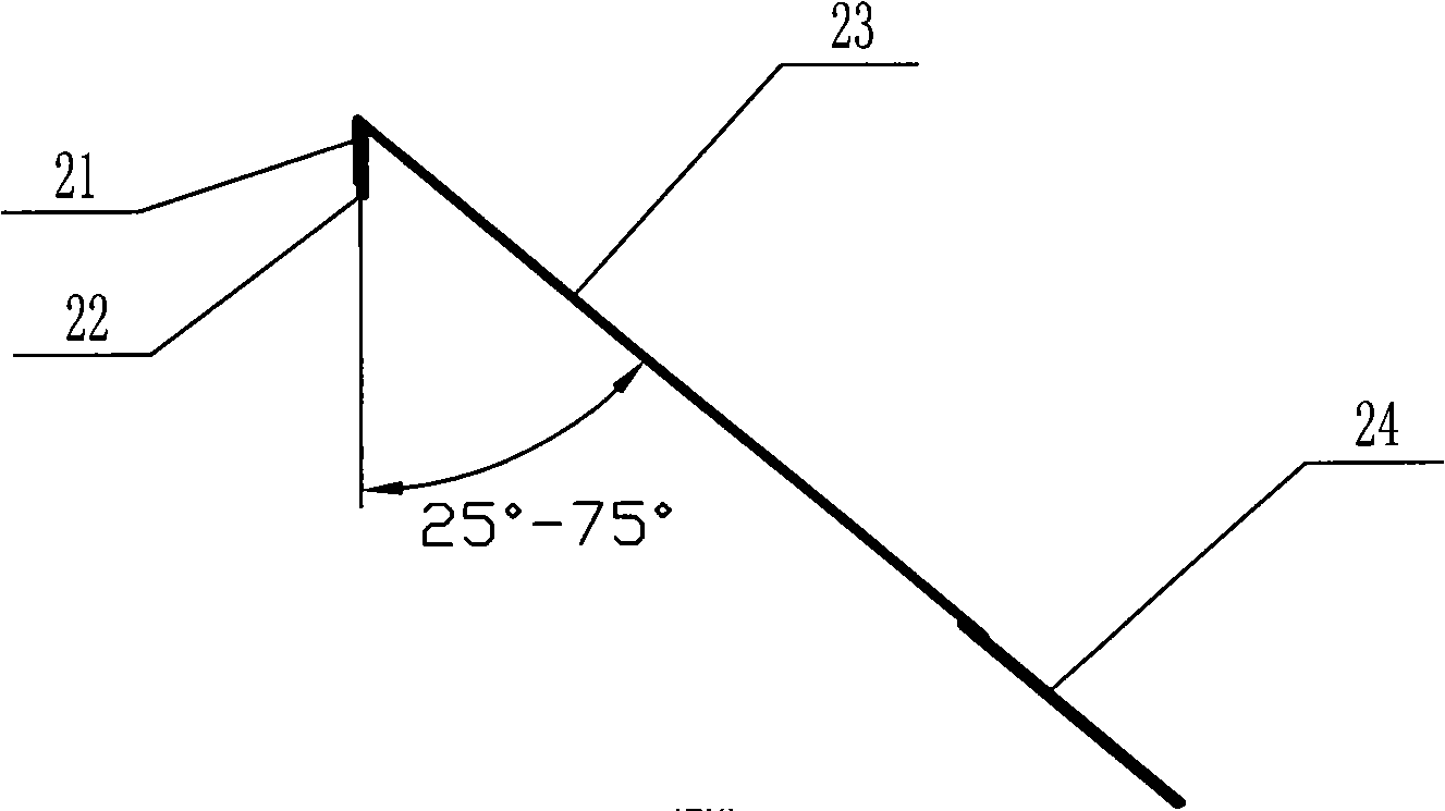
[0044] Embodiment three: see image 3 with Figure 4 , the numbers in the figure are the same as those in Embodiment 1, and the representative meanings are the same, and the same parts will not be repeated. The difference is that the lower end of the expanded steel mesh 23 for hanging the fire grate 12 is provided with a linear leg 24, and the leg 24 is connected to the The side walls of the inner case 9 are in contact.


PUM


Abstract

The invention discloses a high-temperature combustion-supporting device and a backfire biomass fuel dedicated combustion device. The high-temperature combustion-supporting device comprises a ring-shaped body. The inner surface of the ring-shaped body is inverted-cone-shaped or inverted-regular-pyramid-shaped, the outer circumferential surface thereof matches the inner shell shape of the combustion device. The ring-shaped body has integrated structure or combined structure. The dedicated combustion device comprises an inner shell, a water jacket and an outer shell. An upper grate and a lower grate are arranged inside the inner shell. A feed port and a high-temperature fume outlet penetrate the inner shell, the water jacket and the outer shell. An ash outlet is formed at the lower part of the inner shell. The high-temperature combustion-supporting device is arranged on the inner shell wall below the upper grate. A dedusting shroud is arranged on the inner shell relative to the high-temperature fume outlet. A dedusting mesh is arranged at the lower port of the dedusting shroud. A secondary air inlet penetrates the inner shell, the water jacket and the outer shell. The high-temperature combustion-supporting device and the backfire biomass fuel dedicated combustion device have the advantages of reasonable design, complete combustion, suitability for various fuels and good social and economic benefits.

Description

1. Technical field: [0001] The invention relates to a combustion device, in particular to a high-temperature combustion supporter and a special combustion device for backfired biomass fuel. 2. Background technology: [0002] Biomass fuel is a fuel that is directly used by compression molding of crop straw, wood chips, sawdust, peanut shells, corn cobs, rice husks, branches, leaves, and hay. Without any additives and binders. It is a renewable clean energy. According to the requirements of the "Renewable Energy Law" of the People's Republic of China, the National Development and Reform Commission organized the compilation of the "Renewable Energy Medium and Long-Term Development Plan" in August 2006, and proposed the development goals and tasks of renewable energy from 2010 to 2020. , Biomass solid briquette fuel reached 1 million tons and 50 million tons respectively, and established the status of biomass solid briquette fuel as a modern clean energy. [0003] At present,...

Claims


Application Information

Patent Timeline
IPC IPC(8): F23M5/00F24H1/24F24H9/18F23H3/04
Inventor 曾庆普彭世润曹靳果彭国柱
Owner HENAN DERUN BOILER
Why Eureka
Try Eureka