Gas delivery pipeline drag reducer and preparation thereof

A technology for conveying pipelines and drag reducers, which is applied in the field of polymer compound compositions and pipeline systems, can solve problems such as limited drag reduction effects, and achieve the effects of convenient operation, mild reaction conditions, and reduced turbulence

Active Publication Date: 2008-12-24
PIPECHINA SOUTH CHINA CO
View PDF2 Cites 41 Cited by
  • Summary
  • Abstract
  • Description
  • Claims
  • Application Information

AI Technical Summary

Problems solved by technology

However, although this patent proposes a method of applying drag reducers in gas pipelines and some substances of

Method used


Image

  • Gas delivery pipeline drag reducer and preparation thereof
  • Gas delivery pipeline drag reducer and preparation thereof
  • Gas delivery pipeline drag reducer and preparation thereof

Examples


Embodiment 1

[0022] Add 10 parts of pyridine and 8 parts of diisopropylamine into a three-necked flask, stir for 15 minutes, and add 10 parts of formaldehyde solution to the mixed solution at a reaction temperature of 35°C for 1 hour to react, and add 12 parts of benzene to the above solution. Add formic acid, dropwise add 60-75ml of deionized water at the same time, stir and react for 3-4 hours, remove water and purify to obtain the product.

Embodiment 2

[0024] Add 10 parts of pyridine and 10 parts of diisopropylamine into a three-necked flask, stir for 15 minutes, and add 15 parts of formaldehyde solution to the mixed solution at a reaction temperature of 40°C for 1 hour to react, and add 15 parts of benzene to the above solution. Add formic acid, dropwise add 60-75ml of deionized water at the same time, stir and react for 3-4 hours, remove water and purify to obtain the product.

Embodiment 3

[0026] Add 10 parts of pyridine and 15 parts of diisopropylamine into a three-necked flask, stir for 15 minutes, and add 15 parts of formaldehyde solution to the mixed solution at a reaction temperature of 36°C for 1 hour to react, and add 15 parts of benzene to the above solution. Add formic acid, dropwise add 60-75ml of deionized water at the same time, stir and react for 3-4 hours, remove water and purify to obtain the product.

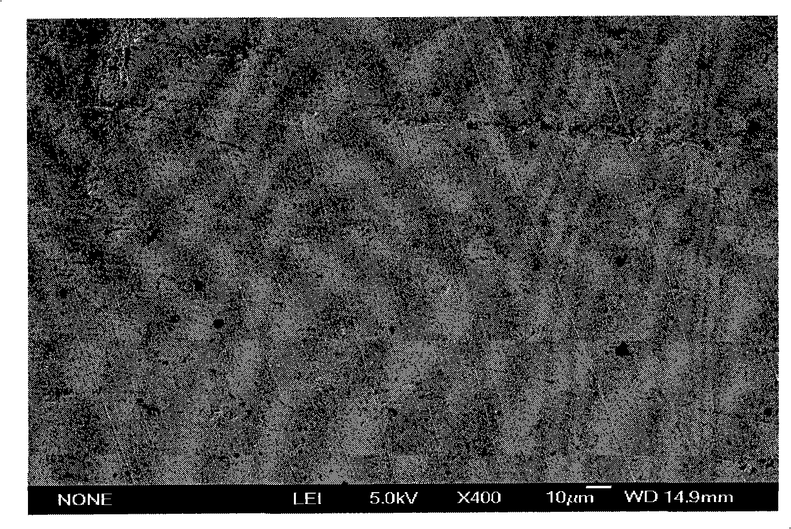
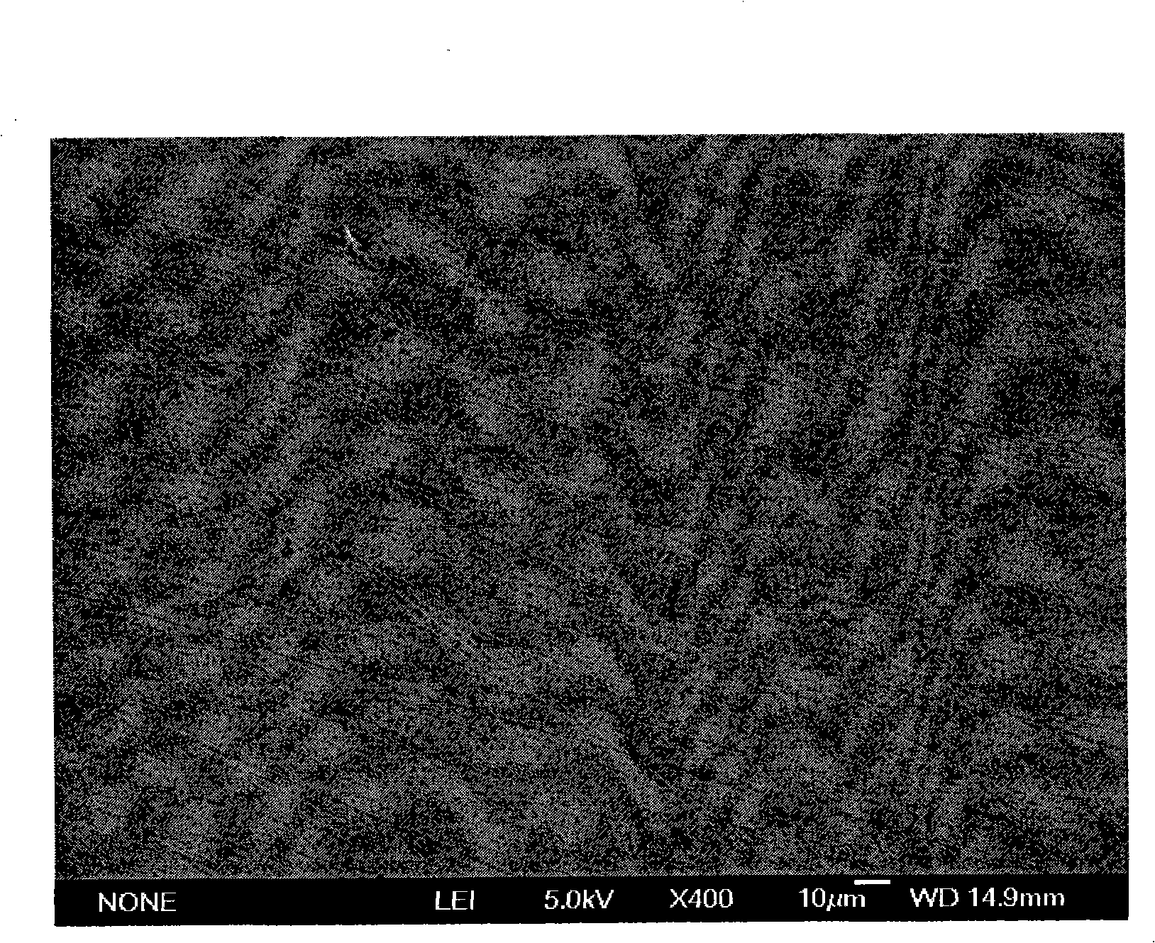
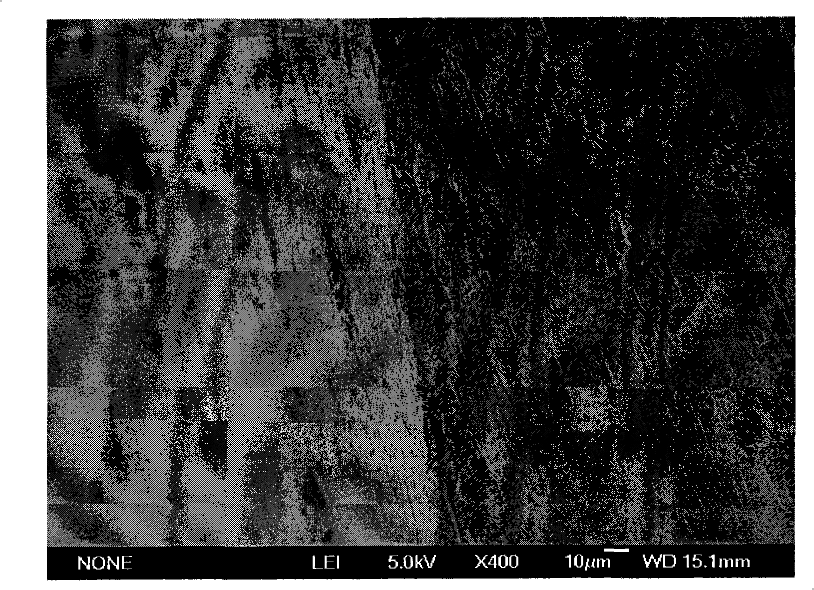
[0027] The product of above-mentioned embodiment is carried out film-forming process and electron microscope analysis, and the result is as follows: Figure 1 ~ Figure 4 shown.

[0028] A certain amount of this product is dissolved in an appropriate amount of absolute ethanol, the steel sheet is processed (oil removal, rust removal, and polished with metallographic paper), and the above solution is sprayed on the processed steel sheet with a spray device. Microscopic analysis was performed on a JEDL JSM-6700F scanning electron microscope.

[0029...


PUM


Abstract

The invention relates to a gas conveying pipeline drag reducer used in gas and particularly natural gas conveying pipeline drag reduction and a preparation method thereof, relating to a macromolecular compound composition and the pipeline system technical field. The gas conveying pipeline drag reducer is characterized in that: the drag reducer consists of pyridine, secondary amine, formaldehyde or acetaldehyde, aromatic acid and deionized water; when total weight is counted as 100 percent, the compositions in percentage by weight are: 10 to 20 percent of the pyridine, 20.4 to 28.4 percent of the secondary amine, 7.6 to 8.4 percent of the formaldehyde or the acetaldehyde, 37 to 38.4 percent of the aromatic acid and 13 to 15 percent of the deionized water. The preparation method comprises the following steps that: the pyridine and the secondary amine in proportional quantities are added in a container and are mixed evenly; the formaldehyde or the acetaldehyde in proportional quantity is dripped to carry out reaction; the aromatic acid in proportional quantity is added, and the deionized water in proportional quantity is dripped so as to carry out reaction continuously; and finally, redundant water is removed, and a target product is obtained after purification. The gas conveying pipeline drag reducer has direct source of raw materials; moreover, the preparation method has simple process, convenient operation and moderate reaction conditions, and a product prepared by the method has excellent drag reduction effect.

Description

technical field [0001] The invention relates to a gas transmission pipeline drag reducer for drag reduction of gas, especially natural gas transmission pipelines, and a preparation method thereof. It relates to the technical field of polymer compound composition and pipeline system. Background technique [0002] The utilization of natural gas energy is one of the important development directions at home and abroad. Due to the global requirements for sustainable economic development and the call for "clean energy", the demand for natural gas is increasing day by day. [0003] At present, the main transportation mode of natural gas is pipeline transportation. Gas pipelines in the modern sense have a history of nearly 120 years. As the gas flows through the pipe, the roughness causes friction which in turn creates a gas vortex, causing energy loss and thus pressure loss in the pipe. For natural gas pipeline transportation in a state of turbulent flow, the pipe wall roughnes...

Claims


Application Information

Patent Timeline
IPC IPC(8): C10M105/70F17D1/02C10M105/58C10M105/28C10M105/20C10N50/02C10N30/06
Inventor 李国平李春漫鲍旭晨刘兵徐海红
Owner PIPECHINA SOUTH CHINA CO
Why Eureka
Try Eureka