

Method for making microfluid system
A technology of a microfluidic system and a production method, which is applied in the field of microfluidic system production, can solve problems such as difficult compatibility, poor biocompatibility, and difficult application of dielectric elastic materials, and achieve good biocompatibility and low cost effects
Inactive Publication Date: 2010-11-10
XI AN JIAOTONG UNIV
View PDF0 Cites 0 Cited by
- Summary
- Abstract
- Description
- Claims
- Application Information
AI Technical Summary
Problems solved by technology
However, due to the characteristics of polymer materials, dielectric elastic materials are not compatible with the commonly used silicon-based MEMS processing technology, and it is difficult to realize the application of dielectric elastic materials in miniaturized devices. Therefore, the biocompatibility is poor, and it is difficult to meet many applications. Occasion use requirements
Method used
View moreImage
Smart ImageViewing Examples

Examples
Embodiment Construction
Login to View More PUM
 Abstract
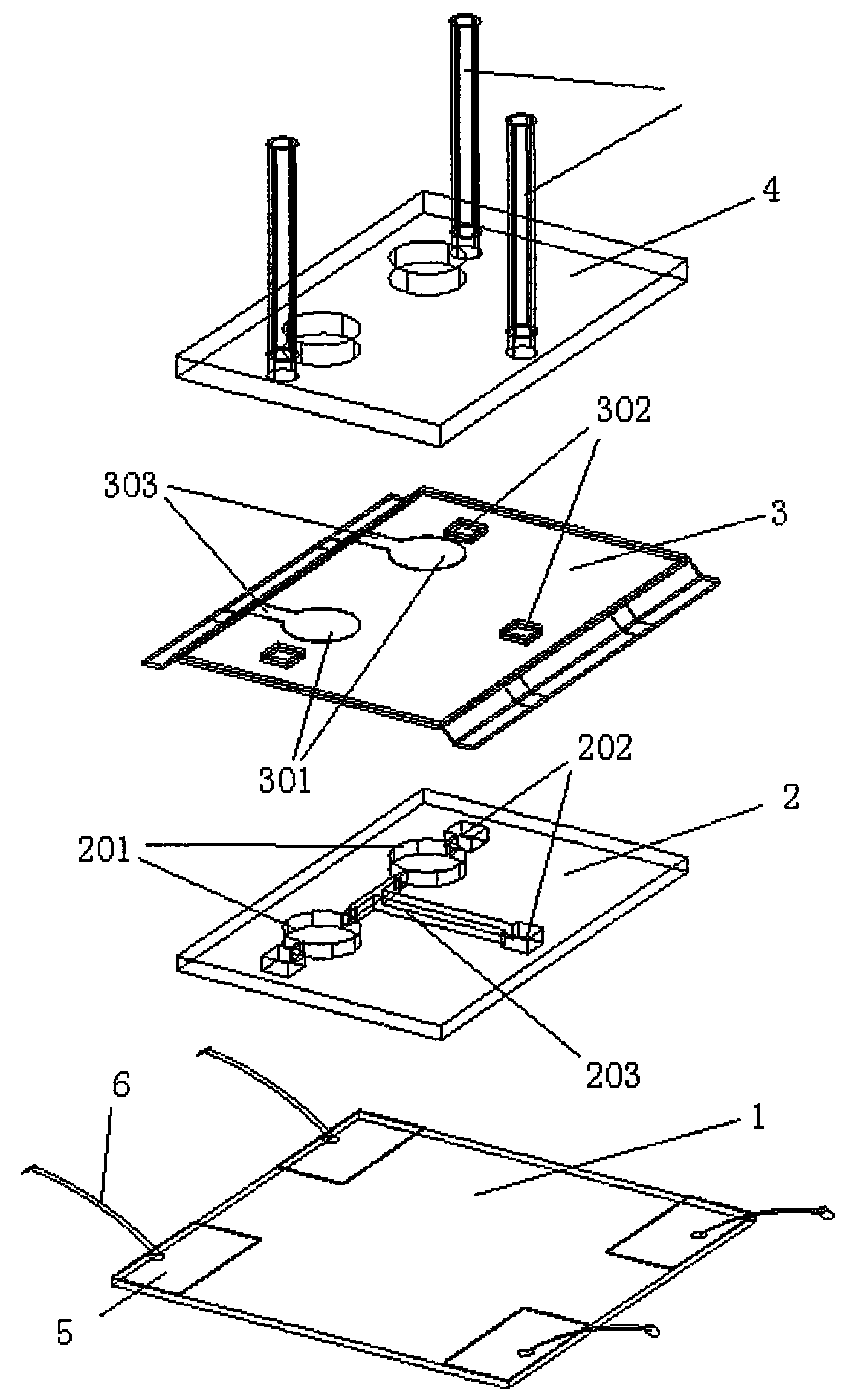
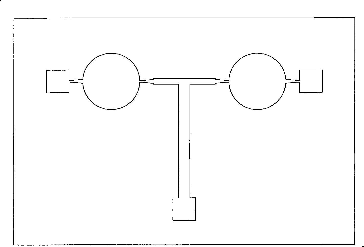
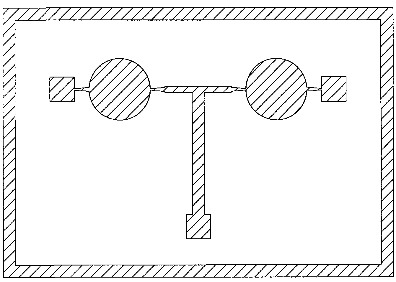
The invention relates to a micro-fluidic system and discloses a preparation method of a micro-fluidic system; the preparation method includes the following steps: choosing optical resist SU-8, carrying out spin coating and baking on a glass wafer for producing a substrate of the micro-fluidic system, adopting UV-LIGA thick ultraviolet photoresist lithography to produce a cavity of the micro-fluidic system; adopting VHB4910 thin-film material from the 3M company, USA, as a vibration film layer which is coated with electric conductive carbon paste to form a pumping diaphragm and an internal lead; arranging a through hole which is corresponding to a liquid in and out port and a micro-pump chamber on a piece of organic glass according to the size of the cavity structure of the micro-fluidic system; adopting VHB9473 thin-film material from the 3M company as a bonding layer, covering the vibration film layer on the bonding layer by aligning, arranging liquid in and out through holes on the vibration film layer and the bonding layer, pressure connecting the organic glass on the vibration film layer and the bonding layer by aligning, placing the product at room temperature for bonding; finally, installing a liquid in and out pipe, and leading out the internal lead by electric connection.
Description
A method of making a microfluidic system technical field The invention relates to a microfluidic system, in particular to a manufacturing method of a microfluidic system. technical background Microfluidic systems based on micromachining and manufacturing technology are an important branch of microelectromechanical systems (MEMS). Because it has the characteristics of small size, good integration, low power consumption, high control precision, fast response speed, etc., and the processing and bonding process are compatible with integrated circuits, it is easy to realize the integration of fluid devices such as micro pumps, micro valves, and micro flow sensors. The integration of control circuits is conducive to mass production, making this miniaturized and integrated microfluidic system widely used in microchemical analysis and detection, micro liquid or gas distribution, printer inkjet array, heat dissipation and cooling of integrated circuit chips, micro components Lubri...
Claims
Login to View More Application Information
Patent Timeline
 Patent Type & AuthorityPatents(China)
IPC IPC(8): B81C1/00
Inventor陈花玲王万军庞宣明李博夏冬梅景素芳朱子才
OwnerXI AN JIAOTONG UNIV